


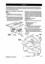
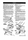
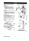

INSTALLING THE FRONT RAIL
See Figures 15and 16.
• Getthe front rail the switchassembly, and the
followinghardware:
6 squarehead botts(5/16-18 x 1 in.)
6 fiatwashers (5/16 in.)
6 hex nuts (5/16-18)
2 screws(1/4-20 x 3/8 in.) (locatedon switch plate)
2 squarenuts (1/4-20) (located on switchplate)
Rightand left end caps for front rail
2 screws(5/32-32 x 1/2 in.)
• Set aside end capsand screwsuntilyou have
alignedthe dp fence and front rail.
• Insertthe sixsquare head boltsinto the table and
extensions,so the bolt heads extend outward 112
in.
• Looselyattach a washer and a hex nut toeach bolt.
• The backof the rail hastwo slots.Slidethe upper
slotover the bolts. (Bottom slotisfor switch.)
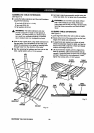
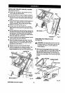
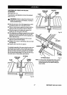
• Alignthe rail left to fight - Matchthe 7-1/8 in. mark
on the dghtscale to the dghtedge ofthe table saw
base (main table). See Figure 16.
• Snugthe railagainst table. Finger-tighteneach nut
onthe table and extensions.
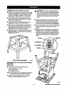
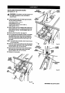
• Locatethe switchassembly. The two screws are
installedthroughthe backofthe switchplate with
thesquare nuts extendingout toward thefront.
Note: The square nutsare looseon the switchplate.
• Slidethe square nuts intothe lowerslotof therail.
• Slidethe switchassembly toa convenientposition,
leavingample clearance for the haedwheeLTighten
securelywitha screwdriver. Do nottightenthe rail
bolts.
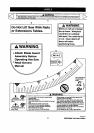
A_ WARNING: Place the switchout ofthe
immediatework area to avoid accidentally
turningit offdudng operation.
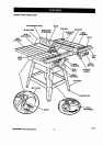
TABLE
TABLE
EXTENSION
SOUARE
HEADBOLTS
TABLE
EXTENSION
SCALE
FRONTRAIL
HEXNUT
FLAT
WASHER
Fig.!5
ENDCAP
SCREW
TABLE
EXTENSION
_IRIn.MARK
R_HTBCALE
SWITCH.
WITHKEY