


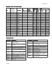
Component Ident
ification
Component Ide
ntification
GG
PC
DG
EM
PA
PB
PT
MP
DB
GB SB
GA
SA
BA
BB
FA
FB
HC
SC
HA
HB
(FM)
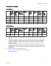
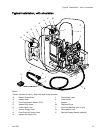
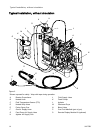
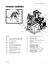
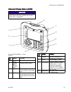
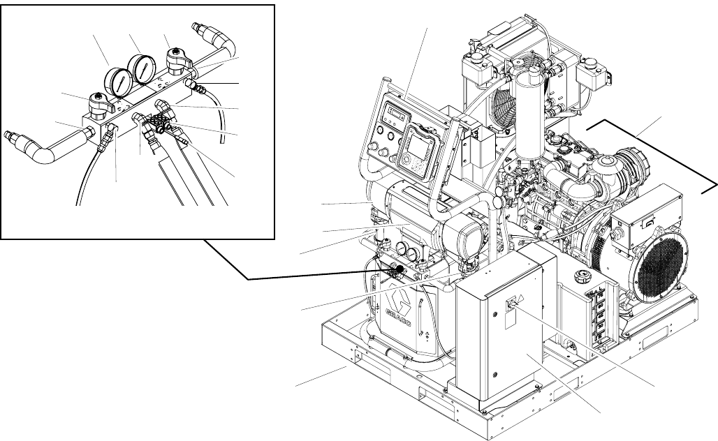
Front V
iew
Figure
3
BA
Compon
ent A Pressure Relief Outlet
BB
Compo
nent B Pressure Relief Outlet
DG Drive
Gear Housing
DB Electrical Enclosure
EM Electric Motor
FA
Comp
onent A Fluid Manifold Inlet
FB
Comp
onent B Fluid Manifold Inlet
FM
Reac
tor Fluid Manifold
GA Com
ponent A Pressure Gauge
GB Com
ponent B Pressure Gauge
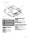
GG Gen
erator, page 17
HA
Com
ponent A Hose Connection
HB
Co
mponent B Hose Connection
HC Heated Hose Electrical Connectors
MP
Main Power Switch
PA
Component A Pump
PB
Component B Pump (behind Electrical
Enclosure)
PC Prop
ortioner Control Panel, page 18
PT Pallet
SA Com
ponent A PRESSURE
REL
IEF/SPRAY Valve
SB Com
ponent B PRESSURE
REL
IEF/SPRAY Valve
SC Fl
uid Temperature Sensor (FTS) Cable
TA
Co
mponent A Pressure Transducer
(b
ehind gauge GA)
T
B
Component B Pressure Transducer
(behind gauge GB)
3A1705J 15