


Setup
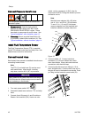
Electrical Co
nnections
Connect air compressor, breathing air, and auxiliary
power electrical connections to the specified circuit
breakers. See Circuit Breakers, page 28.
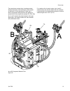
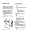
1. Remove one or more knock-outs on side
of electrical enclosure, as required, and
route wires through for air compressor,
breathing air, and auxiliary equipment. See
Circuit Breaker Configuration Options, page 29,
for more information.
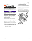
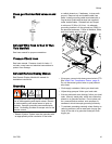
Connect Feed Pumps
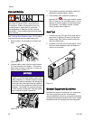
1. Install feed pumps (K) in component
A and B supply drums. See
Typical Installation, with circulation, page 13 and
Typical Installation, without circulation, page 14.
2. Seal component A drum and use desiccant dryer
(M) in vent.
3. Install agitator (L) in component B drum, if
necessary.
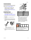
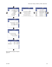
4. Connect supply hoses from feed pumps to the
component A and component B material inlets
on the system. Ensure A and B inlet valves are
closed.
Note
Supply hoses from feed pumps should
be 3/4 in. (199 mm) ID.
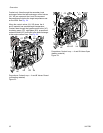
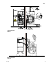
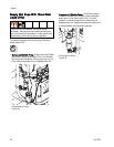
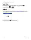
5. Connect air lines to proportioner. Ensure
components are properly connected to correct
location.
PF
PG
PJ
PH
Ref Air Outlet
PF A Pump
PG
BPump
PH Agitator
PJ
Gun
Note
Agitator air supply (PH) includes a small
internal restriction orifice to limit the air
flow to minimize air compressor load.
Maximum supplied air flow is 2.0 scfm
(0.1 m3/min) at 100 psi (0.7 MPa, 7 bar).
Designed for use with Twistork agitator
224854. Do not use the agitator air outlet
(PH) for any other component.
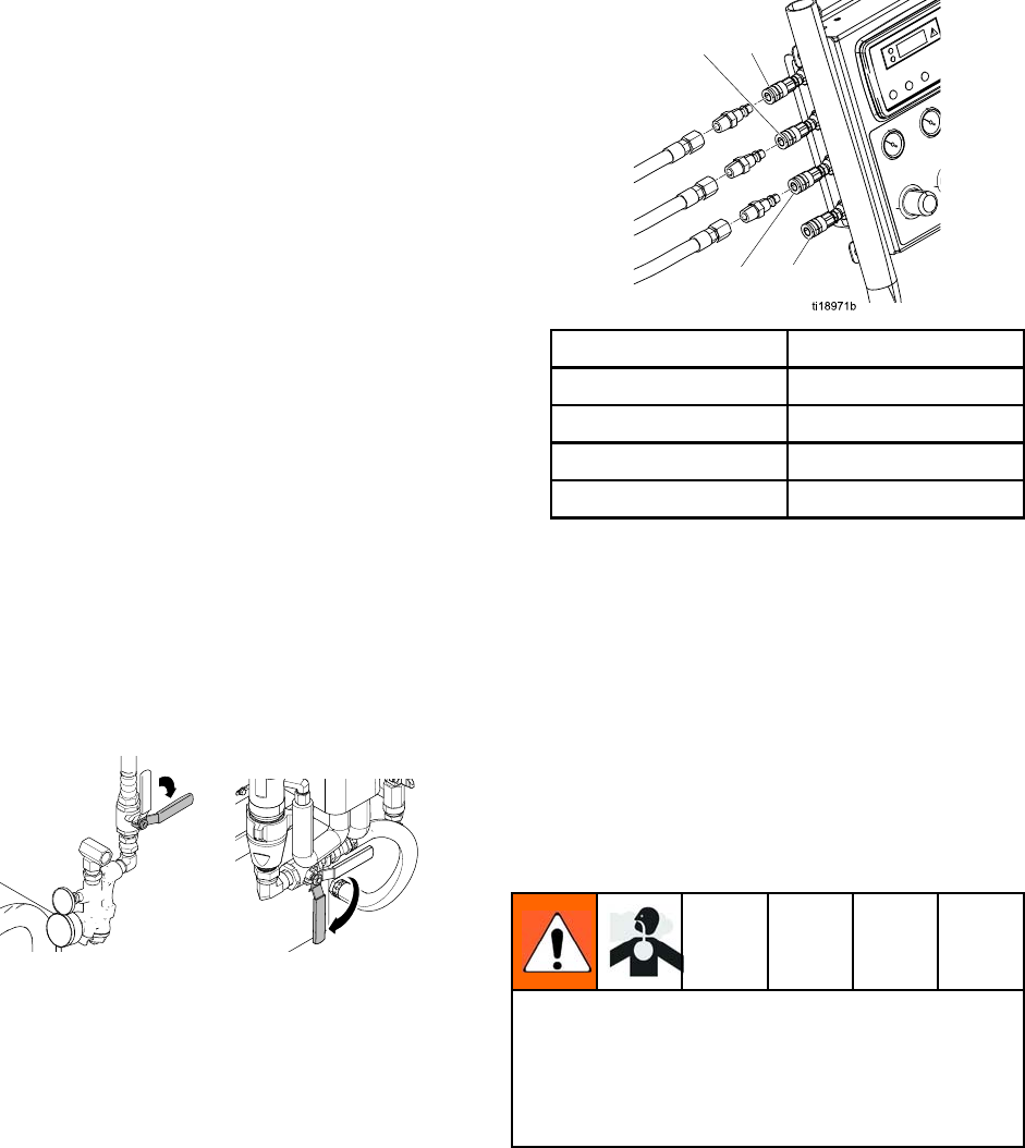
Breathing Air
Breathing the air from the compressed air supply
can cause serious injury if inhaled.
•Onl
y use an independent and approved
bre
athing air system with adequate air flow to
pro
vide clean breathable air.
3A1705J 39