


Setup
Connect Press
ure Relief Lines
Do not operate Reactor without all covers and
shrouds in place.
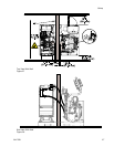
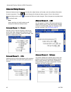
1. Recommended: Connect high pressure
hose (R) to relief fittings (BA, BB) of both
PRESSURE RELIEF/SPRAY valves. Route
hose back to component A and B drums. See
Typical Installation, with circulation, page 13.
2. Alternately: Secure supplied bleed tubes (N)
in grounded, sealed waste containers (H). See
Typical Installation, without circulation, page 14.
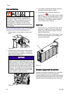
Install Fluid Temperature Sensor
The Fluid Temperature Sensor (FTS) is supplied.
Install FTS between main hose and whip hose. See
Heated Hose manual for instructions.
Connect Heated Hose
See Heated Hose manual for detailed instructions on
connecting heated hoses.
Note
The FTS (C) and whip hose (D) must be used
with heated hose. Hose length, including
whip hose, must be 60 ft (18.3 m) minimum.
NOTICE
Apply grease on all system and hose fluid fittings.
This lubricates the threads and prevents material
from hardening on the threads.
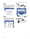
1. Turn main power switch OFF .
2. Assemble heated hose sections, FTS, and whip
hose.
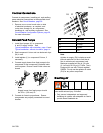
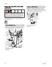
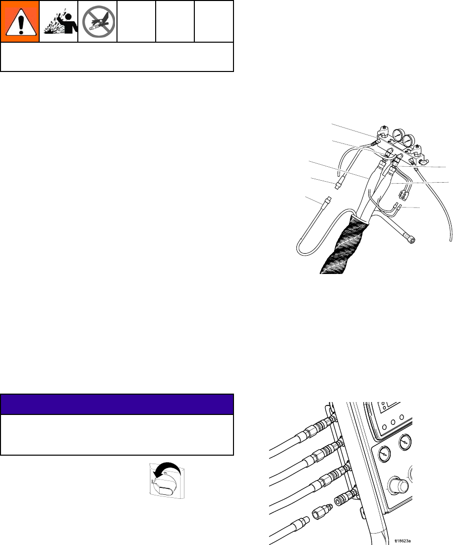
3. Connect A and B hoses to A and B outlets on
Reactor fluid manifold (FM). Hoses are color
coded: red for component A (ISO), blue for
component B (RES). Fittings are sized to prevent
connection errors.
Note
Manifold hose adapters (HA, HB) allow
use of 1/4 in. and 3/8 in. ID fluid hoses.
To use 1/2 in. (13 mm) ID fluid hoses,
remove adapters from fluid manifold and
install as needed to connect whip hose.
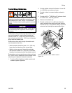
FM
HA
A
V
B
HB
C
SC
Figure 32
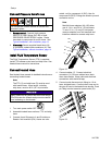
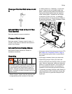
4. Connect cables (C). Connect electrical
connectors (V). Be sure cables have slack
when hose bends. Wrap cable and electrical
connections with electrical tape.
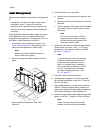
5. Connect quick-disconnect pin fitting to 4 ft air
hose, shipped loose. Connect other hose end to
the gun air hose in the heated hose bundle. Push
pin fitting into the lowest air panel outlet (PJ).
Figure 33
40 3A1705J