


Maintenance
Drain Coolant
To avoid burns, do not perform maintenance on
the coolant system until the coolant system has
reached ambient temperature.
Drain coolant from the engine and proportioner
coolant loops once a year or if the coolant lines need
to be disconnected, in order to install a wall between
the generator and proportioner.
1. Perform Shutdown, page 63.
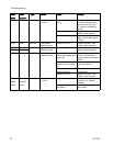
2. Remove the cabinet door from the front of the
proportioner.
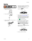
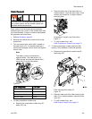
3. Turn on manual valve switch (MV), located on
the load center (LC), to manually open the A
and B heat exchanger control valves and bypass
control valve.
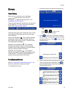
Note
The battery must be connected to
operate valves. The load center (LC)
LEDs will stay on when the manual valve
switch (MV) is in the ON position.
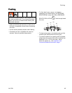
LC
MV
Figure 40
LED Component LED Color
Manualvalveswitch(MV)
Red
A Side Control Valve
Red
B Side Control Valve
Blue
Bypass Valve
Green
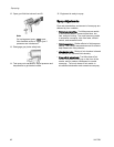
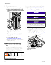
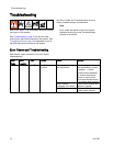
4. To drain proportioner coolant loop:
a. Remove the proportioner coolant loop fill
bottle (HF) cap.
b. Place the other end of the drain tube in a
waste container. Open the drain valve. Drain
coolant until coolant is no longer visible in
the sight glass.
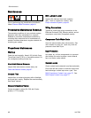
Proportioner Coolant Loop Drain Valve
Figure 41
c. To refill coolant loop, see
Refill Proportioner Coolant Loop, page 70.
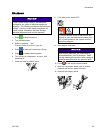
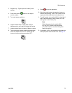
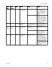
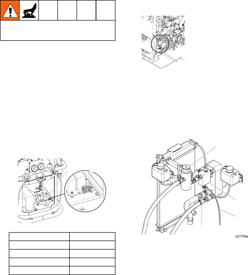
5. To drain proportioner coolant loop from filter
housing. Only available on Series B systems.
a. Remove the proportioner coolant loop fill
bottle cap (HF).
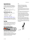
D
H
T
HF
Filter Housing Drain Valve (D)
Figure 42
b. Place the other end of the filter housing drain
tube (T) in a waste container. Open the drain
valve (D).
c. To refill coolant loop, see
Refill Engine Coolant Loop, page 72.
3A1705J 69