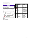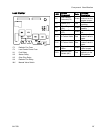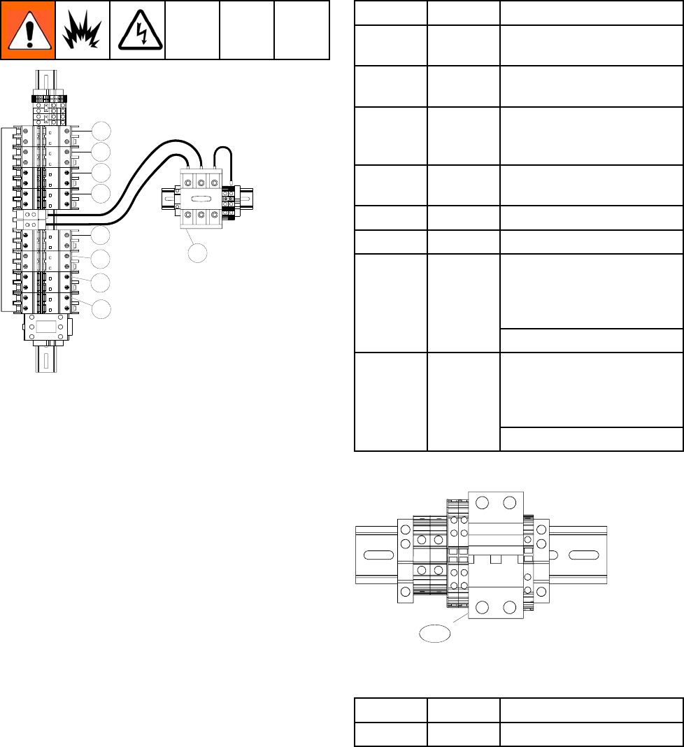
Component Ident
ification
Circuit Break
ers
CB01
CB02
CB03
CB04
CB05
CB06
CB07
CB08
CT01
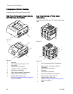
Circuit B
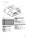
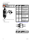
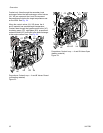
reakers Inside Electrical Enclosure (DB)
Figure 1
8
Note
Not all wires are shown.
Ref. Size Component
CB01
30 A High Power Tem
perature
Control Modu
le (HPTCM)
CB02
20 A
Motor Control Module
(MCM)
CB03
5A
Two Motor Fans, Cabinet
Fan, Power Supply, and
Coolant Circulation Pump
CB04*
30 A
Auxiliary
Power (Air
Compress
or)
CB05*
10 A Auxiliary Power
CB06*
20 A Auxilia
ry Power
E-XP2i and E-30i With
Heat: Low Power
Temperature Control
Module (LPTCM) A
CB07
15 A
E-30i:
Auxiliary
E-XP2i and E-30i With
Heat: Low Power
Temperature Control
Module (LPTCM) B
CB08 15 A
E-30i: Auxiliary
*SeeCircuit Breaker Configuration Options, page 29.
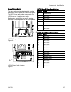
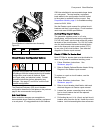
CB20
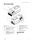
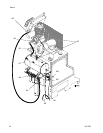
Circuit Breakers Inside Proportioner Cabinet
Figure 19
Ref. Size Component
CB20
5
0A
H
eated Hose
28 3A1705J


