


Setup
Setup
NOTICE
Proper system setup, startup, and shutdown
procedures are critical to electrical equipment
reliability. The following procedures ensure steady
voltage. Failure to follow these procedures will
cause voltage fluctuations that can damage
electrical equipment and void the warranty.
NOTICE
Do not remove or separate the proportioner, engine
assembly, or power distribution box from the pallet.
Failure to leave the component mounting intact will
cause heating efficiency degradation, and potential
unsafe wiring and grounding.
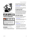
Locate Reactor
If system was not ordered with the air compressor,
go to step 2.
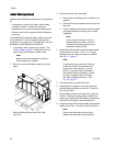
1. Forsystemswithanaircompressor, install the
air tank bracket assembly and connect air lines.
For systems without an air compressor, order air
compressor kit 24K335. See manual 3A1902 for
complete installation instructions.
NOTICE
Only use air compressors with a
continuous run head unloader. Repeated
compressor motor startups will cause
errors and shutdown the system. See
Technical Specifications, page 102 for
recommended air compressors and
requirements. Other models may be used, but
motor must not stop and start during operation.
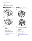
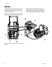
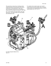
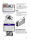
a. Use at least two people to install the air
tank assembly (AT). Secure to frame with
supplied screws (AS) and nuts (AN). See
illustration on next page.
b. Remove u-bolt holding desiccant container
and add all desiccant pellets (shipped
separately). Replace u-bolt securely. See
manual 309921.
c. Connect air line (A1) between compressor
and air tank inlet.
d. Connect air line (A2) between proportioner
air inlet to air dryer outlet.
e. Connect pilot air lines (A3 and A4) between
the air compressor and air tank.
f. Secure water drain lines (A5 and A6) to the
frame and drain outlets.
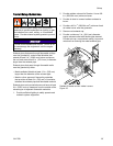
2. Install hose rack, if ordered. See manual 3A1903
for detailed instructions.
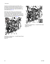
3. Locate Reactor on a level surface that is
nonporous and diesel resistant, such as diamond
plate. See Dimensions, page 96, for clearance
and mounting hole dimensions.
Note
Leave at least 1 ft. (0.3m) distance from
the engine side of the pallet to any wall
for engine maintenance access. See
Fig. 27, page 37.
4. Do not expose Reactor to rain or below 20°F
(-7°C).
NOTICE
To ensure the heat exchanger control valves
open and close properly, do not store Reactor
below 20°F (-7°C).
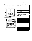
5. If a wal
l will be installed between the
propor
tioner and generator, remove
the fue
l tank and battery bracket. See
Traile
r Setup Guidelines, page 35 for instructions.
6. To mou
nt in a trailer, use forklift to move Reactor
by ins
erting the forks through the Reactor pallet
frame
. It is recommended to lift from the engine
side.
Bolt pallet directly to trailer frame.
Note
Use Pallet Support Kit 24L911 (rollers not
included) to relocate pallet to mounting
location when forks are unavailable. See
kit manual for instructions.
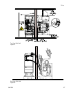
NOTICE
Kee
p the vent holes in the bottom of the
pro
portioner cabinet open. Make sure there is
un
obstructed incoming air for the cooling fan at the
to
p of the proportioner cabinet that blows air up into
th
e electric motor. Failure to provide unobstructed
in
coming air can cause the motor to overheat.
3A1705J 33