Maintenance
Engine Maintenance
The engine ins
tructions that accompany your
unit detail sp
ecific procedures for maintenance of
the engine. Fo
llowing the engine manufacturer’s
recommendati
ons will extend engine work life.
Daily
• Cooling System Coolant Level — Check
• Engine Air Cleaner Service Indicator — Inspect
• Engine Oil Level — Check
Every 500 Se
rvice Hours or 1 Year
• Engine Air Cleaner Element (Dual Element) —
Clean/Replace
• Engine Oil and Filter — Change
• Fuel System Filter — Replace
• Battery Voltage — Check. See
Appendix A: Engine Control Module, page 93.
Contact an Authorized Perkins Dealer or Distributor
for replacement filter elements. Refer to Perkins
engine part number GN66141N for compatible parts.
Fuel Tan
k
Fuel quality is critical to the performance and to the
service life of the engine. Water in the fuel tank
can cause excessive wear to the fuel system. See
the supplied Perkins engine manual for fuel tank
maintenance recommendations.
Flush
Inlet Strainer Screen
The inlet strainers filter out particles that can plug the
pump inlet check valves. Inspect the screens daily as
part of the startup routine, and clean as required.
Isocyanate can crystallize from moisture
contamination or from freezing. If the chemicals used
are clean and proper storage, transfer, and operating
procedures are followed, there should be minimal
contamination of the A-side screen.
Note
Clean the A-si
de screen only during
daily startup
. This minimizes moisture
contaminatio
n by immediately flushing
out any isocya
nate residue at the start of
dispensing op
erations.
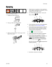
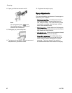
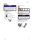
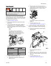
1. Close the fluid inlet valve at the pump inlet and
shut off the appropriate feed pump. This prevents
material from being pumped while cleaning the
screen.
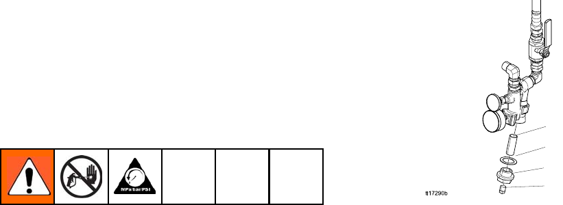
2. Place a container under the strainer base to catch
drain off when removing the strainer plug (C).
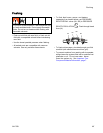
3. Remove the screen (A) from the strainer
manifold. Thoroughly flush the screen with
compatible solvent and shake it dry. Inspect the
screen. No more than 25% of the mesh should
be restricted. If more than 25% of the mesh is
blocked, replace the screen. Inspect the gasket
(B) and replace as required.
4. Ensurethepipeplug(D)isscrewedintothe
strainer plug (C). Install the strainer plug with the
screen (A) and gasket (B) in place and tighten.
Do not overtighten. Let the gasket make the seal.
5. Open the fluid inlet valve, ensure that there are
no leaks, and wipe the equipment clean. Proceed
with operation.
A
B
C
D
Figure 38
3A1705J 67


