


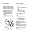

Component Ident
ification
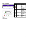
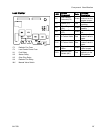
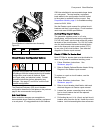
CB10
Circuit Breakers Inside Alternator Assembly
Figure 20
Ref. Size Component
CB10
90 A 120/240V Alternator
Circuit Breaker Configuration Options
Improper configurat
ion can result in electric shock.
All changes from the
recommended circuit breaker
configuration must
meet all National, State,
and Local safety an
d electrical codes. Consult
a qualified electri
cian before attempting any
changes. See page 2
7 and 28 for correct circuit
breaker configura
tion.
The Electrical Enclosure (DB) circuit breaker
configuration described in the tables on the previous
page is the recommended configuration.
Sub-Panel Options
Some customer changes are acceptable to
accommodate larger loads from auxiliary equipment
or a sub-panel. It is suggested that circuit breakers
CB04 be substituted to accommodate larger loads
or a sub-panel. The total auxiliary equipment
loads added to the configuration must be limited
to the system’s available auxiliary current. See
Proportioner Models, page 9, for available auxiliary
current at 240V, 60Hz.
See the React
or repair manual for optional circuit
breakers and
their current ratings. Circuit breakers
used must mee
t UL489 specifications.
Auxiliary Wiring Diagram Options.
The generator supplies power in a 3-wire,
single-phase, mid-point neutral wiring configuration.
For 240 VAC loads, wire the load across the output
terminals of the circuit breaker. For 120 VAC loads,
wire the load between the neutral terminal blocks
next to the three pole main power switch (CT01)
to one pole of the circuit breaker. See electrical
diagrams in Reactor repair manual.
Disable L
PTCMs For Booster Heat
Both LPTCMs for booster heat must be disabled to
allow use of power for additional auxiliary power.
1. Follow Shutdown instructions. See
Shutdown, page 63.
2. Refer to Disable Optional Booster Heater Wiring
Diagram in the Reactor repair manual.
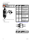
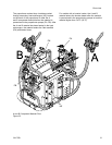
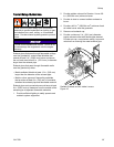
To repl
ace or repair a circuit breaker, use the
follow
ing steps:
1. Follow Shutdown instructions. See
Shutdown, page 63.
2. Refer to circuit breaker identification table and
electrical diagrams in Reactor repair manual.
3. Loosen four screws connecting wires and bus
bar to circuit breaker that will be replaced.
Disconnect wires.
4. Pull locking tab out 1/4 in. (6mm) and pull circuit
breaker away from the din rail. Install new circuit
breaker. Insert wires and tighten down all screws.
3A1705J 29