


Component Ident
ification
Motor Control
Module (MCM)
MB
MA
1A
10
1B
2
3
12
MC
5
13
6
7
11
8
9
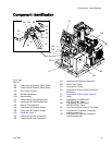
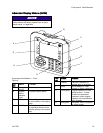
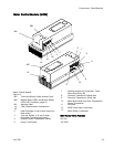
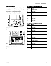
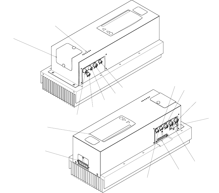
Motor Control Module
Figure 10
MA
Token and Rotary Switch Access Cover
MB
Module Status LEDs see Module Status
LEDs (CN) Conditions, page 20
MC
Warning Label
1A,
1B
CAN Communication Connections
2
Heat Exchanger Control Vave Output (to
load center)
3
Two-way Splitter to A and B Heat
Exchanger Temperature Sensors
5
E
ngine Coolant Temperature Sensor
6
P
ump Cycle Switch
7
Opti
onal Accessory Connection: Feed
Pump
Shut Down Kit
8
Pre
ssure Transducer B (Blue) side
9
Pre
ssure Transducer A (Red) side
10
Mot
or Brush Wear and Over-Temperature
Sen
sor Connection
11 Not used
12
MC
M Power Input Connection
13
Mo
tor Power Connection
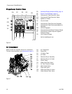
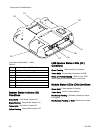
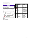
MCM Rotary Switch Positions
0
=E-30i
1=E-XP2i
3A1705J 23