


G0675 10" Jointer/Planer Combo Machine
-15-
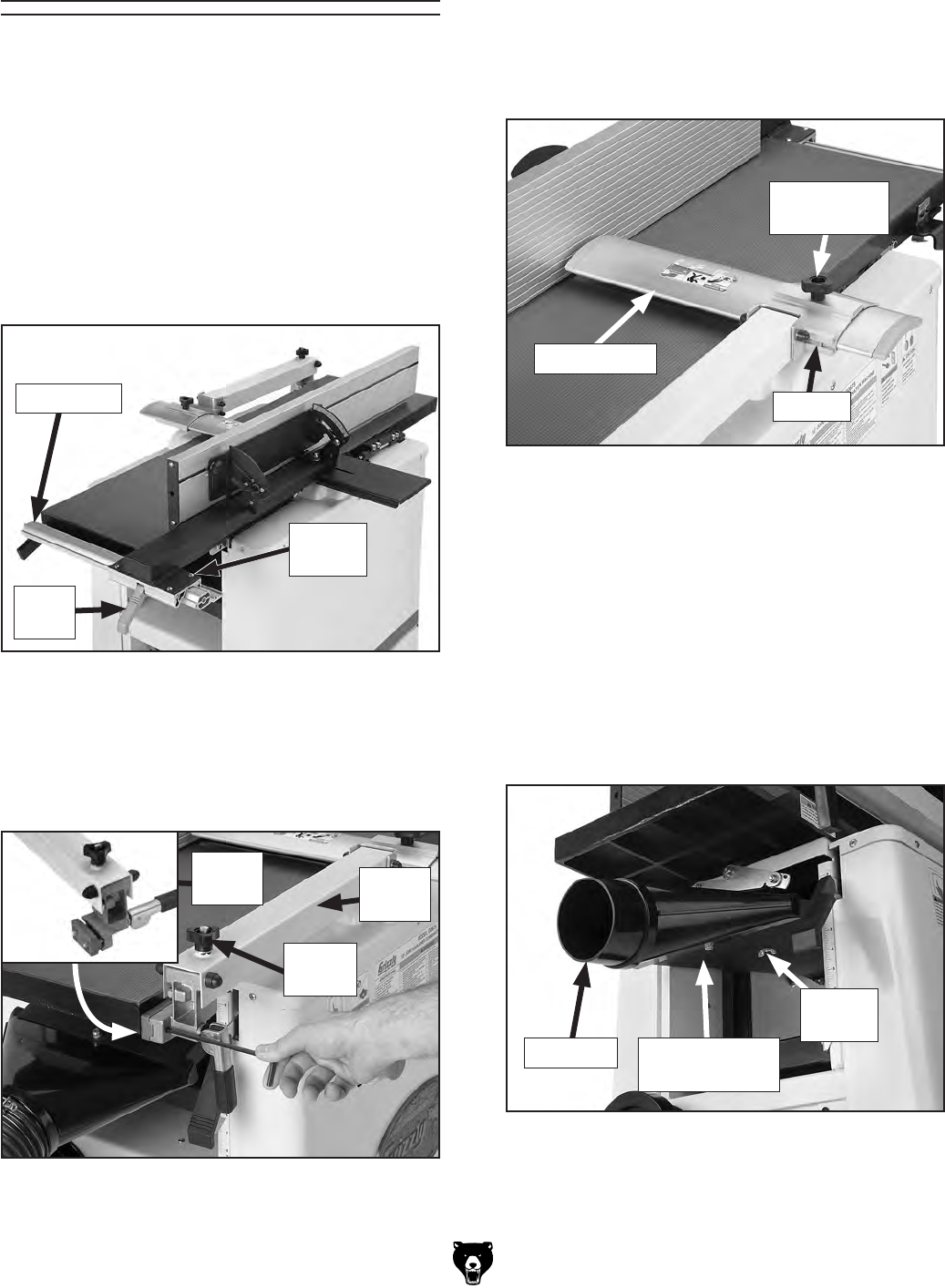
Assembly
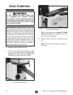
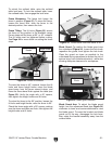
Figure 12. Blade guard installed.
3. Loosen the guard lock knob, slide the blade
guard into the bracket, then tighten the lock
knob (see Figure 12).
Blade Guard
Guard Lock
Knob
To raise the blade guard, turn the height
adjustment knob counterclockwise (Figure
11); to lower the blade guard, turn the knob
clockwise.
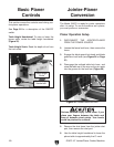
4. Loosen the thumb screw on the dust hood
assembly, insert the dust port into the dust
hood assembly, then tighten the thumb screw
(see Figure 13). Make sure the fingers on the
dust hood slide all the way into the grooves
on the port.
Figure 13. Installing dust port.
Dust Hood
Assembly
Dust Port
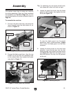
2. Engage the blade guard lever, align the cap
screws on the arm with the mounting holes
on the outfeed table, then tighten the screws
(see detail in Figure 11).
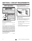
This section covers how to setup your machine
for jointing operations. Once you have completed
the assembly and Test Run (Page 18), you can
convert the machine for planer operation (refer to
Page 22).
To assemble the machine:
1. Pull up on the fence lock lever, then place the
fence assembly onto the table fence rail, as
shown in Figure 10.
Figure 10. Fence installed.
Figure 11. Blade guard arm installed.
Tip: Try tightening one cap screw several turns,
then repeat with other until both are tight.
Bracket
Guard
Arm
Guard
Lever
Height
Knob
Thumb
Screw
Lock
Lever
Fence Rail
Handle
Bracket