


-48-
G0675 10" Jointer/Planer Combo Machine
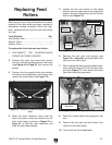
11. Place the chain back onto the feed roller
sprockets, rolling it on in the same manner
that you removed it in Step 7.
12. Re-install the springs and hex nuts onto both
sides of the new feed rollers, tightening the
nuts until they are
1
⁄2" (13mm) from the bot-
tom of the bolts, as shown in Figure 74 on
Page 46.
13. Remove the hex wrench to re-tension the
chain.
14. Re-install the flat belt, making sure that it is
seated into the infeed wheel grooves, then
secure the cap screws on the wheel bracket
and the infeed belt wheel.
15. Check the flat belt tension (refer to Page 33,
Step 6).
16. Re-install the infeed table with the bolts and
washers you removed earlier, and reinstall
the side panels with the cap screws.
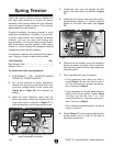
Chain Tension
The chain drive transfers movement from the
handwheel to elevate the headstock. The chain
drive can be adjusted to remove slack if the chain
stretches over time or is loosened during table
leveling procedures.
This procedure will require you to remove the
jointer/planer assembly from the base to adjust
the chain tension.
Tools Needed: Qty
Wrench or Socket 13mm ................................... 2
Forklift ................................................................ 1
Sawhorses ......................................................... 2
To adjust the chain tension:
1. DISCONNECT THE JOINTER/PLANER
FROM THE POWER SOURCE!
2. Perform Steps 2–7 in the Table Parellelism
Adjustments subsection on Page 50, except
you will not need to remove the side panels—
unless you plan to check table parallelism
after checking chain tension.
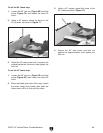
4. Using the forklift, place the table back on
the base, and relatch the base to the jointer/
planer.
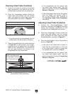
Figure 79. Underside of table and idler sprocket.
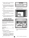
NOTICE
During the next step, DO NOT let the chain
fall off the sprockets—returning it to its
proper location without changing the table
adjustments can be very difficult.
3. Loosen the two lock nuts on the idler sprocket
(Figure 78 and 79) and move the sprocket
behind the chain to tighten it.
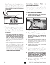
Figure 78. Top idler sprocket lock nut (viewed
from planer table infeed side).
Lock Nut
Idler Sprocket
Lock Nut
(Hidden by
Sprocket)