


-40-
G0675 10" Jointer/Planer Combo Machine
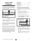
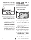
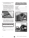
Straightedge
Outfeed Table
0.060"
Feeler Gauge
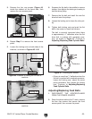
Figure 59. Using feeler gauge to check outfeed
table-cutterhead height.
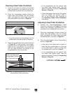
Note: The back side of the outfeed table is
factory set approximately 0.060" from the
cutterhead. The back side of the outfeed
table is not adjustable, so any adjustments to
parallelism must be made on the front of the
outfeed table.
5. Place the straightedge on the front side of the
outfeed table so it hangs over the cutterhead,
as shown in Figure 59, then try to fit a
feeler gauge or combination of feeler gauges
between the cutterhead and bottom of the
straightedge.
—If the feeler gauge slides with slight resis-
tance between the ruler and cutterhead
and no gaps appear between the straight-
edge and the table, then the outfeed table
is already parallel with the cutterhead. Go
to Checking Infeed Table Parallelism on
Page 41.
—If the feeler gauge does not fit between the
ruler and cutterhead, or if there is a gap
between the straightedge and the table,
the outfeed table is not parallel with the
cutterhead. Correct the outfeed table paral-
lelism, then correct the infeed table paral-
lelism. Continue to Correcting Outfeed
Table to Cutterhead Parallelism.
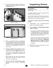
Correcting Outfeed Table to
Cutterhead Parallelism
This procedure involves loosening the outfeed
table support blocks and adjusting their height to
raise or lower the front of the outfeed table until it
is parallel with the cutterhead.
To correct outfeed table parallelism:
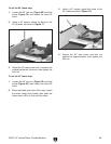
1. Loosen the cap screws on both outfeed table
support blocks (see Figure 60).
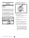
2. Fit the 0.060" feeler gauge (or combination
of feeler gauges) onto the front side of the
cutterhead, then place the straightedge on
the front of the outfeed table and over the
feeler gauge.
3. While an assistant holds the feeler gauge and
straightedge, adjust the height of each sup-
port block until no gaps appear between the
straightedge and the table.
4. Tighten the cap screws on the suport blocks
to secure the adjustment.
5. Using the straightedge and the 0.060" feeler
gauge, verify again that no gaps appear
between the table and the straightedge.
6. Repeat Steps 1 –5 until the front outfeed table
parallelism is correct, then repeat Checking
Outfeed Table Parallelism on Page 39 to
ensure the outfeed table height above the
cutterhead is equal across the table.
7. Continue to Checking Infeed Table
Parallelism on Page 41.
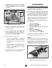
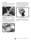
Figure 60. Location of front outfeed table
support blocks.
Cap Screw
Support Blocks