G0675 10" Jointer/Planer Combo Machine
-45-
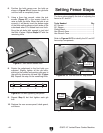
To set the 90˚ fence stop:
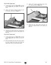
1. Loosen the 90˚ lock nut (Figure 69) and stop
screw (Figure 70), and loosen the fence tilt
locks.
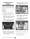
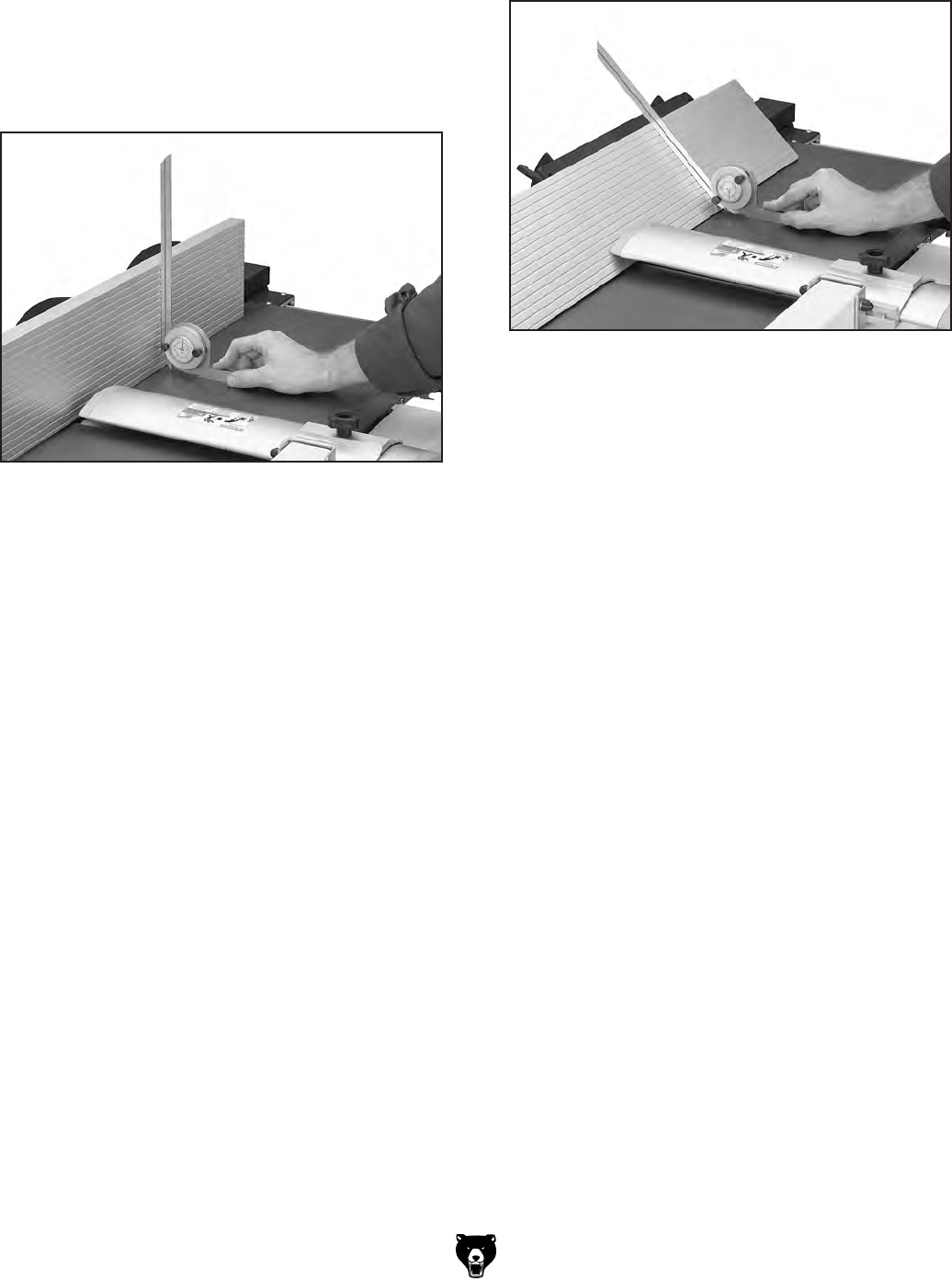
2. Using a 90˚ square, adjust the fence to the
90˚ position, as shown in Figure 71.
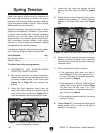
4. Secure the 45° stop screw and lock nut
against the angled bracket, then tighten the
lock nut.
Figure 71. Adjusting fence to 90˚.
3. Adjust the 90˚ stop screw until it contacts the
angled bracket on the fence, then tighten the
lock nut.
To set the 45˚ fence stop:
1. Loosen the 45˚ lock nut (Figure 70) and stop
screw (Figure 69), then loosen the fence tilt
locks.
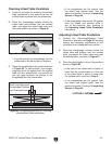
2. Move the blade guard out of the way, loosen
the fence height lock knobs, then slide the
fence down until it is flush with the table.
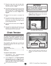
3. Using a 45° square, adjust the fence to the
45° outward position (Figure 72).
Figure 72. Adjusting fence 45˚ outward.


