


G0675 10" Jointer/Planer Combo Machine
-21-
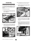
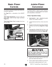
Figure 22. Fence tilt controls.
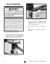
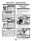
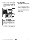
Blade Guard: To position the blade guard over
the cutterhead (Figure 24), loosen the lock knob,
reposition the guard, then tighten the lock knob.
Place the guard as close as possible to the
cutterhead during operations to reduce the risk of
serious injury from cutterhead contact—while also
allowing adequate clearance for workpieces.
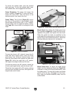
Figure 23. Fence bevel flush with table at 45°.
To move the fence to 45° outward, loosen the tilt
locks and fence height knobs, move the blade
guard away from the fence several inches, and
move the fence bevel flush against the table (see
Figure 23). Verify the angle with a 45° square,
then tighten the height knobs and tilt locks.
To return the fence to the 90° position, loosen the
tilt locks and height knobs, raise the fence to 90°.
Check the fence angle with a 90° square, making
sure the fence and table are flush, then tighten the
height knobs and tilt locks.
Fence Movement: The fence lock keeps the
fence in position (Figure 21). To move the fence,
loosen the fence lock, slide the fence to the
desired position, then secure the lock.
Fence Tilting: The tilt locks (Figure 22) secure
the fence at any position in the available range.
Fence stops set the fence at 90° or 45° outward.
The tilt locks must be tightened before cutting.
See Page 44 for more detail on setting the fence
stops.
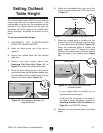
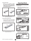
To unlock the outfeed table, raise the outfeed
table lock lever. To lock the outfeed table, lower
the outfeed table, then engage the lock lever.
Tilt
Locks
Adjustment
Knob
Lock Knob
Lock Lever
Figure 24. Blade guard controls.
Blade Guard Arm: To adjust the blade guard
height, turn the adjustment knob (see Figure 24)
clockwise to lower and counterclockwise to raise
the blade guard. To move the bracket and blade
guard out of the way, disengage the lock lever,
then rotate the bracket assembly away from the
outfeed table.
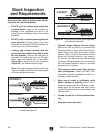
Angle Scale
Fence Height
Knobs
Bevel