


-50-
G0675 10" Jointer/Planer Combo Machine
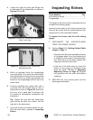
If you do not have a Rotacator, a wood block and
feeler gauges may be used, but extra care must
be taken to ensure accuracy. If the table is not
within the maximum allowable tolerances, it must
be adjusted.
7. Move the Rotacator to the same position
under the outfeed side of the planer table and
note the reading.
Table Parallelism Adjustments
The table is adjusted by turning the chain sprock-
ets underneath the base. This procedure can take
a great deal of patience and time.
To adjust the table parallelism:
1. DISCONNECT THE JOINTER/PLANER
FROM THE POWER SOURCE!
2. Convert the machine for jointer operations,
then remove the fence, fence arm assembly,
and lock the outfeed table.
3. Remove the front and rear access panels,
then unlatch the jointer/planer assembly from
the base.
4. Place sawhorses about 16 inches apart.
5. Place forklift forks under both tables, making
sure they do not contact the outfeed table
lock lever or the infeed table height lever, but
enough so the machine does not slide off of
the forks.
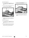
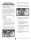
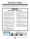
6. While an assistant steadies the jointer tables,
lift the machine off of the base and set it onto
the sawhorses, as shown in Figure 84.
Figure 84. Machine supported by sawhorses.
3. Rock the cutterhead back and forth and
rotate the cutterhead until the dial is at "0".
4. Move the Rotacator to the same position on
the oppposite side of the table and note the
reading.
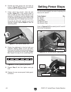
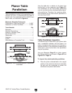
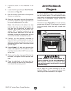
5. Place the Rotacator on the base under the
center of the infeed side of the planer table,
so the plunger contacts the webbing evenly
(see Figure 83).
6. Lower the table and zero out the Rotacator.
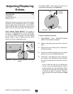
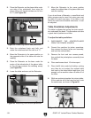
Figure 82. Measuring side-to-side parallelism.
2. Place the Rotacator on the planer table under
one side of the cutterhead, then raise the
planer table until the dial rotates one full turn
to "0" (see Figure 82).
Table
Cutterhead
Figure 83. Measuring front-to-back parallelism.
Table
16"
Base