


G0675 10" Jointer/Planer Combo Machine
-23-
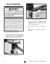
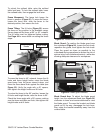
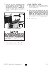
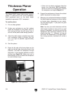
7. Swing the dust chute assembly clockwise
over the cutterhead, then push it down onto
the infeed table until you hear a "click"—this
indicates that the lock lever (Figure 27) has
secured the infeed table. The lever must
engage the infeed table for the planer to
operate.
8. Install the dust port onto the dust chute with
the thumb knob, as shown in Figure 27, then
install the dust hose with a hose clamp.
The dust chute must be secured during
planer operations or the machine will not
operate. If the machine DOES operate when
the dust chute lock is disengaged, immedi-
ately DISCONNECT THE JOINTER/PLANER
FROM POWER and call Technical Support.
Figure 27. Dust chute secured.
Dust Port
Thumb Knob
Lock
Lever
Jointer Operation Setup
1. Reverse Steps 2–8 in the previous subsec-
tion. You must push the catch lever back to
release the dust port.
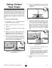
2. While holding the outfeed table up, push
the lock arm pin out to fold the lock arm in
and lower the outfeed table most of the way
(Figure 26). When the table is close to the
frame, raise the outfeed table lock lever,
lower the table the rest of the way, then push
the lever down to secure the outfeed table.
3. Re-install the fence.