


G0675 10" Jointer/Planer Combo Machine
-47-
Replacing Feed
Rollers
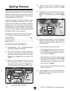
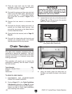
4. Move the chain tensioner away from the
chain and place a 5mm hex wrench into the
hole in the frame, as shown in Figure 73 on
Page 46, to hold the chain tensioner and
keep the chain detensioned.
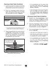
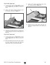
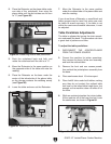
Figure 76. Wheel bracket cap screws.
Infeed
Belt
Wheel
Wheel Bracket
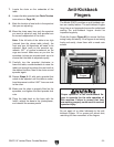
5. Loosen the four cap screws on the wheel
bracket, and one cap screw on the infeed belt
wheel, raise the infeed wheel and roll the flat
belt off (see Figure 76).
Sprocket
Wheel
8. Raise the outfeed table and engage the lock
arm.
9. Remove the front and rear feed rollers, then
install the new feed rollers.
10. Close and lock the outfeed table.
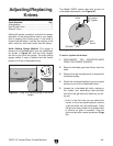
After long term use of the jointer/planer the rubber
coating on the feed rollers may wear, resulting in
workpieces feeding erratically. When this hap-
pens, replace both the front and rear feed rollers
as a set.
Tools Needed: Qty
Hex Wrench 4mm .............................................. 1
Wrench 13mm ................................................... 1
Wrench 10mm ................................................... 1
To replace the front and rear feed rollers:
1. DISCONNECT THE JOINTER/PLANER
FROM THE POWER SOURCE!
2. Remove the eight cap screws that secure
the front and rear access panels to the frame
(see Figure 44 on Page 33), then remove the
panels.
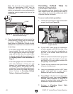
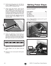
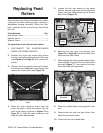
3. Remove the four special bolts and washers
that secure the infeed table to the frame, then
remove the infeed table (see Figure 75).
Figure 75. Location of bolts that secure infeed
table.
Bolts
6. Remove the hex nuts and springs (see
Figure 73 on Page 46) from both sides of the
front and rear feed rollers.
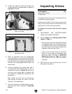
7. While rotating the lower sprocket wheel clock-
wise, walk the chain off of the front feed roller
sprocket (Figure 77), then remove the chain
from both feed roller sprockets.
Figure 77. Removing feed roller chain.
Front Feed Roller
Sprocket
Cap
Screws