


G0675 10" Jointer/Planer Combo Machine
-33-
6. Squeeze the flat belt in the middle to remove
tension, then tighten the locking nut nearby to
hold the drive pulley.
7. Remove the flat belt and install the new flat
drive belt onto the pulleys.
8. Loosen the locking nut to lower the drive pul-
ley.
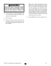
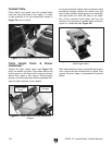
9. Tighten both locking nuts and push the flat
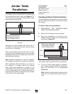
belt in the center to check belt tension.
The belt is correctly tensioned when there
is approximately
1
⁄2" deflection when the flat
drive belt is pushed with moderate pres-
sure, as shown in Figure 47. Continue to
Adjusting /Replacing Feed Cylinder Belts.
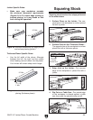
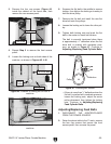
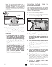
3. Remove the four cap screws (Figure 44)
inside the cabinet on the fence side, then
remove the rear access panel.
Figure 44. Location of rear access panel screws.
Front View
Rear View
4. Repeat Step 3 to remove the front access
panel.
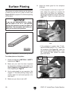
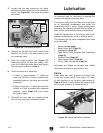
5. Loosen the locking nuts on both sides of the
machine, as shown in Figures 45 & 46.
Motor
Pulley
Locking Nut
Figure 45. Location of locking nut on rear of
machine.
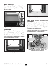
Figure 46. Location of locking nut on front of
machine.
Locking Nut
— If there is more than
1
⁄2" deflection when the
flat belt is pushed with moderate pressure,
loosen the locking nuts, adjust the motor
pulley downward, then tighten the locking
nuts. Continue to Adjusting/Replacing
Feed Cylinder Belts.
Adjusting/Replacing Feed Belts
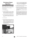
1. DISCONNECT THE JOINTER/PLANER
FROM THE POWER SOURCE!
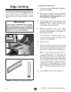
2. Raise the planer table to the 3" mark, remove
the four cap screws that secure the front
access panel, then remove the panel.
Pulley
Deflection
Pulley
Figure 47. Checking belt tension.
1
⁄2"
Cap Screws
Flat Drive Belt