


INPUT AND GROUND CONNECTIONS
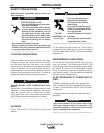
MACHINE GROUNDING
The frame of the welder must be grounded. A ground
terminal marked with the symbol shown is located
inside the reconnect / input access door for this pur-
pose. See your local and national electrical codes for
proper grounding methods.
A-3
INSTALLATION
POWER WAVE® AC/DC 1000
A-3
I
NPUT FUSE AND SUPPLY WIRE
CONSIDERATIONS
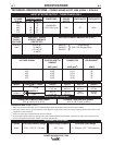
Refer to Specifications page for recommended fuse and
wire sizes. Fuse the input circuit with the recommended
super lag fuse or delay type breakers (also called "inverse
time" or "thermal/magnetic" circuit breakers). Choose input
and grounding wire size according to local or national elec-
trical codes. Using fuses or circuit breakers smaller than
recommended may result in "nuisance" shut-offs from
welder inrush currents, even if the machine is not being
used at high currents.
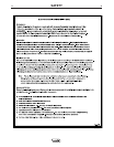
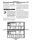
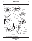
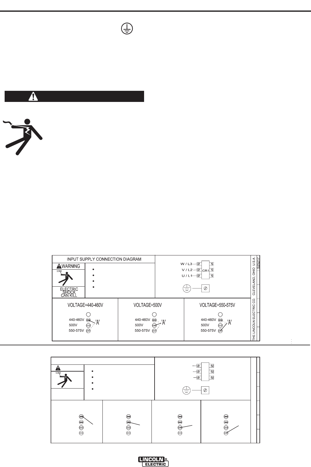
INPUT VOLTAGE SELECTION
Welders are shipped connected for the highest input voltage
listed on the rating plate. To move this connection to a dif-
ferent input voltage, see the diagram located on the inside
of the input access door, or the Reconnect Diagram K2344-
1 and K2344-2 shown below. If the Auxiliary lead (indicated
as ‘A’) is placed in the wrong position, there are two possi-
ble results. If the lead is placed in a position higher than the
applied line voltage, the welder may not come on at all. If
the Auxiliary lead is placed in a position lower than the
applied line voltage, the welder will not come on, and the
two circuit breakers in the reconnect area will open. If this
occurs, turn off the input voltage, properly conne
ct the aux-
iliary lead, reset the breakers, and try again.
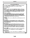
INPUT CONNECTION
ELECTRIC SHOCK can kill.
• Only a qualified electrician should
connect the input leads to the
Power Wave. Connections should
be made in accordance with all
local and National Electrical
Codes and the connection dia-
gram located on the inside of the
reconnect / input access door of
the machine. Failure to do so may
result in bodily injury or death.
-----------------------------------------------------------------------
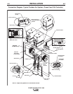
Use a three-phase supply line. A 1.75 inch (45 mm)
diameter access hole for the input supply is located on
the case back. Connect L1, L2, L3 and ground
according to the Input Supply Connection Diagram.
WARNING
Reconnect Diagram for K2344-1 Power Wave AC/DC 1000
XA
Do not operate with covers removed
Disconnect input power before servicing
Do not touch electrically live parts
Only qualified persons should install,
use or service this equipment
Reconnect Diagram for K2344-2 Power Wave AC/DC 1000 ("CE – ready")
S26047
THE LINCOLN ELECTRIC CO. CLEVELAND, OHIO U.S.A.
VOLTAGE=440-460V
'A'
A
500V
U / L1
V / L2
CR1
W / L3
INPUT SUPPLY CONNECTION DIAGRAM
550-575V
ELECTRIC
SHOCK
CAN KILL
WARNING
Do not operate with covers removed
Disconnect input power before servicing
Do not touch electrically live parts
Only qualified persons should install,
use or service this equipment
440-460V
VOLTAGE=500V
'A'
500V
550-575V
440-460V
VOLTAGE=550-575V
'A'
500V
550-575V
440-460V
VOLTAGE=380-415V
'A'
500V
550-575V
440-460V
380-415V 380-415V 380-415V 380-415V