


A-16
INSTALLATION
POWER WAVE® AC/DC 1000
A-16
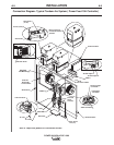
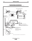
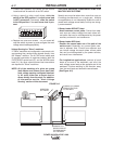
CABLE INDUCTANCE, AND ITS EFFECTS
ON WELDING
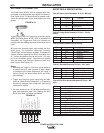
Excessive cable inductance will cause the welding
performance to degrade. There are several factors
that contribute to the overall inductance of the cabling
system including cable size, and loop area. The loop
area is defined by the separation distance between
the electrode and work cables, and the overall welding
loop length. The welding loop length is defined as the
total of length of the electrode cable (A) + work cable
(B) + work path (C) (see Figure A.1 below). To mini-
mize inductance always use the appropriate size
cables, and whenever possible, run the electrode and
work cables in close proximity to one another to mini-
mize the loop area. Since the most significant factor in
cable inductance is the welding loop length, avoid
excessive lengths and do not coil excess cable. For
long work piece lengths, a sliding ground should be
considered to keep the total welding loop length as
short as possible.
REMOTE SENSE LEAD CONNECTIONS
Voltage Sensing Overview
The best arc performance occurs when the Power
Wave AC/DC 1000 has accurate data about the arc
conditions. Depending upon the process, inductance
within the electrode and work cables can influence the
voltage apparent at the studs of the welder, and have
a dramatic effect on performance. To counteract this
negative effect, remote voltage sense leads are used
to improve the accuracy of the arc voltage information
supplied to the control pc board.
There are several different sense lead configurations
that can be used depending on the application. In
extremely sensitive applications it may be necessary
to route cables that contain the sense leads away
from the electrode and work welding cables.
If the remote voltage sensing is enabled but the
sense leads are missing, improperly connected, or
if the electrode polarity switch is improperly con-
figured extremely high welding outputs may
occur.
------------------------------------------------------------------------
Electrode Voltage Sensing
The remote ELECTRODE sense lead (67) is built into
the wire feeder control cable (K1785) and accessible
at the wire drive. It should always connected to the
wire drive feed plate when a wire feeder is present.
Enabling or disabling electrode voltage sensing is
application specific, and automatically configured
through software.
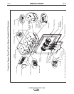
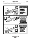
Work Voltage Sensing
For most applications the use of a remote work volt-
age sense lead is recommended. The Power Wave
AC/DC 1000 is shipped from the factory with the
remote work voltage sense lead enabled. It must be
attached to the work as close to the weld as practical,
but out of the weld current path. For more information
regarding the placement of remote work voltage
sense leads, see the section entitled "Voltage Sensing
Considerations for Multiple Arc Systems." The remote
WORK sense lead (21) can be accessed at one of two
locations. Either at the wire drive via the wire feeder
control cable (K1785), or at the four-pin WORK sense
lead connector located under the spring loaded output
cover. Whenever possible, use the WORK sense lead
that is built into wire feeder control cable (K1785)
since it is closely coupled with the ELECTRODE
sense lead and will tend to be more immune to electri-
cal noise. If it is not possible to sense the WORK volt-
age near the feeder, the four-pin WORK sense lead
connector at the power source should be used (a plug
and pigtail assembly is provided for this purpose).
Never connect the WORK sense lead at two differ-
ent locations.
ELECTRIC SHOCK can kill.
• Do not touch electrically live parts or
electrodes with your skin or wet
clothing.
• Insulate yourself from the work and
ground.
• Always wear dry insulating gloves.
-----------------------------------------------------------
Some simplified applications may perform adequately
by sensing the work voltage directly at the WORK
STUD without the use of a remote work voltage sense
lead. If a remote work voltage sense lead is not used,
it must be disabled as follows:
1. Turn off power to the power source at the dis-
connect switch.
2. Remove the front cover from the power source.
B
A
C
POWER
WAVE
FIGURE A.2
WORK
WARNING
CAUTION
CAUTION