


A-12
INSTALLATION
POWER WAVE® AC/DC 1000
A-12
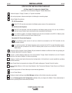
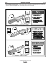
STEP BY STEP INSTALLATION CHECKLIST
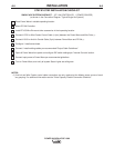
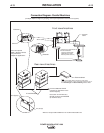
TRIPLE ARC SYSTEM CHECKLIST – (DEVICENET PLC CONTROLLED, 1 POWER SOURCE PER ARC)
(as shown in the Connection Diagram "Typical Triple Arc System”)
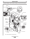
Place Power Waves in suitable operating location.
Mount DeviceNet PLC Controller and User Interface.
Install PF10S Wire Drives and other accessories in their operating location.
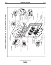
Mount Power Wave System Interface.
Connect K1785-xx Wire Feeder Control Cable (14 pin) between each Power Wave and Wire Drive.
(1)
Connect K1543-xx ArcLink Control Cable (5 pin) from ARC #1 power source to the System Interface input.
(1)
Connect K1795-xx System Control Cables (22 pin) between each Power Wave and the appropriate System
Interface "ARC" (formerly "PHASE") outputs.
(2)
Connect the System Interface and each power source to the PLC via the DeviceNet network.
(1)
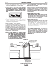
Configure / Install sense leads.
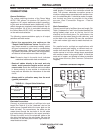
Connect / Install welding cables per recommended "Output Cable Guidelines."
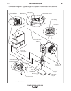
Open all Power Wave front panels and configure DIP switch settings (including the DeviceNet MAC ID and
Baud Rate settings) per "Internal Controls" section.
Connect input power to Power Waves per recommended guidelines.
Turn on Power Waves, and verify all system Status Lights are solid green.
NOTES:
(1) ArcLink, DeviceNet and Wire Feeder control cable connections are only required at the Master power source
of each arc grouping. For additional information see the "Extra Capacity Parallel Connection Checklist."
(2) The "ARC" (formerly "PHASE") connections from the System Interface are only required for the Master
power source of each arc grouping. For additional information see the "Extra Capacity Parallel Connection
Checklist."