


A-24
INSTALLATION
POWER WAVE® AC/DC 1000
A-24
ELECTRIC SHOCK can kill.
• Do not touch electrically live parts
or electrodes with your skin or wet
clothing.
• Insulate yourself from the work and ground.
• Always wear dry insulating gloves.
-----------------------------------------------------------
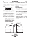
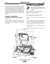
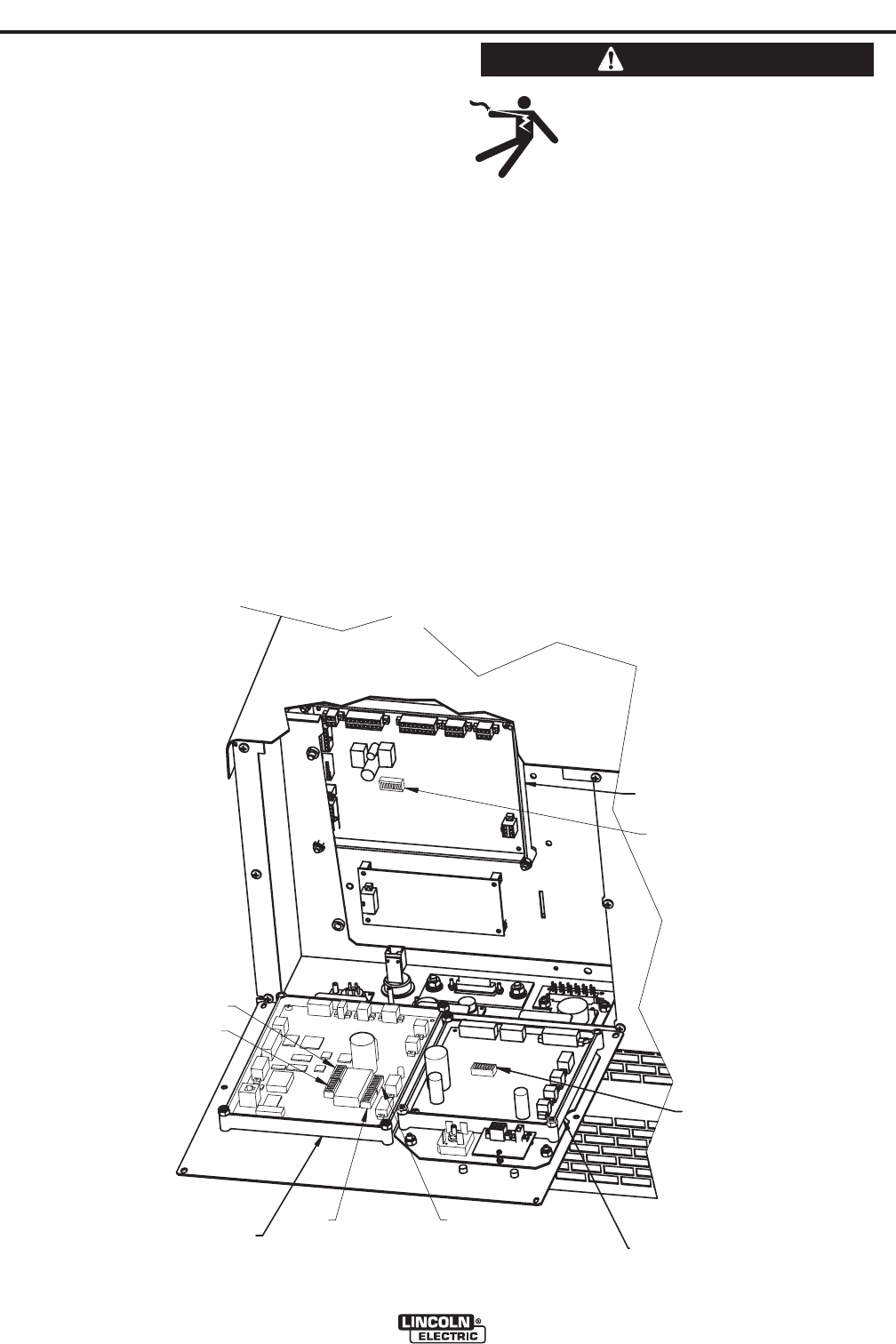
1. Turn off power at the disconnect switch.
2. Remove the screws securing the front access
panel.
3. Open the access panel, allowing the weight of the
panel to be carried by the hinge tab at the bottom.
Make sure the weight of the access panel is sup-
ported by the hinge tabs, not the wiring harness.
4. Adjust the DIP switches as necessary (see infor-
mation below).
5. Replace the panel and screws, and restore power.
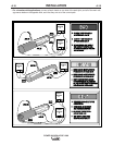
CONTROL
P.C. BOARD
S1
S1
ETHERNET
P.C. BOARD
S1
S2
S4
S3
FEEDHEAD
P.C. BOARD
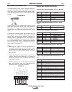
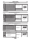
FIGURE A.4
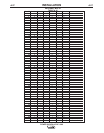
DEVICENET CONFIGURATION
For systems controlled via DeviceNet, The MAC ID
and baud rate must be properly configured (see the
Internal Controls section of this document). Other
information regarding basic system integration of the
Power Wave AC/DC 1000 with a DeviceNet PLC is
provided in the DeviceNet Interface Specification (part
of the Power Wave Submerged Arc Utilities software
package available on CD from the Lincoln Electric
Company).
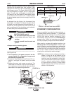
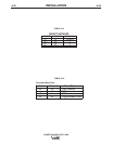
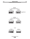
INTERNAL CONTROLS
INTERNAL CONTROLS DESCRIPTION
(See figure A.4)
The P.C. Boards located behind the Power Wave
AC/DC 1000 front access panel are equipped with
DIP switches for custom configuration. To access the
DIP switches:
WARNING