


A-21
INSTALLATION
POWER WAVE® AC/DC 1000
A-21
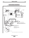
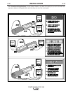
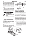
EXTERNAL I/O CONNECTOR
The Power Wave AC/DC 1000 is equipped with a ter-
minal strip for making simple input signal connections.
(See Figure A.2a) The terminal strip is located under-
neath the spring-loaded cover, and divided into three
groups:
FIGURE A.2a
Trigger group, Cold Inch Group and Shutdown Group.
When the Power Wave AC/DC 1000 is controlled via
DeviceNet, the Trigger and Cold Inch Groups can
interfere with the welding sequence and should not be
used.
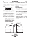
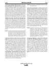
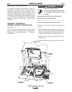
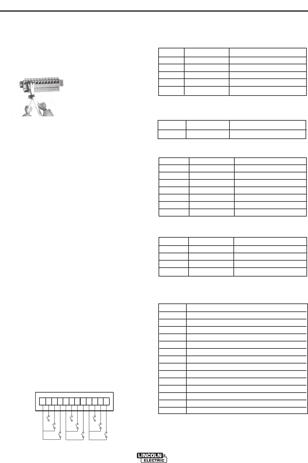
All inputs use "normally open" logic except the shut-
down group. The shutdown inputs use "normally
closed" logic, and are always enabled. Shutdown2 is
typically used for signaling low flow in the water cool-
er. Unused shutdowns must be tied to the +15V sup-
ply for the shutdown group. Machines are shipped
from the factory with jumpers installed on both shut-
down inputs. (See Figure A.3)
Notes:
1. Activating the Trigger or Cold Inch group inputs on
a system without a user interface or other means
of configuring the Weld Sequencer will result in
default values for Weld Mode, WFS and Work
point settings.
2. Trigger and Cold Inch group inputs may be rede-
fined as "Weld Profile Selections" by Production
Monitoring software (see Production Monitoring
Literature for details)
3. On later machines, pin 12 has been redefined as a
gear ratio selection input. See “Setting the Wire
Drive Gear Ratio” for further information.
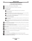
FIGURE A.3
D
E
F
1
2
3
4
5
6
78
9 10
11
12
G
H
I
A
B
C
+15 VDC for Trigger Group
Trigger Input
Dual Procedure Input
4 Step Input
+15 VDC for Cold Inch Group
Cold Inch Forward
Cold Inch Reverse
Gas Purge Input
+15 for shutdown group
Shutdown1 input
Shutdown2 input (Water Fault)
Reserved for future use
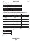
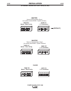
RECEPTACLE SPECIFICATION
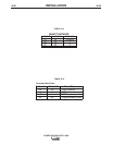
Table A.2 Output Arclink Receptacle S1 (5 pin – MS style)
PIN Lead # Function
A 53 Arclink L
B 54 Arclink H
C 67A Electrode Voltage Sense
D 52 Ground(0v)
E 51 +40vdc
Table A.3 Voltage Sense Receptacle S2 (4 pin – Circular
Plastic)
PIN Lead # Function
3 21A Work Voltage Sense
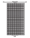
Table A.4 RS232 Connector S3 (DB-25 style)
PIN Lead # Function
2 253 RS232 Receive
3 254 RS232 Transmit
4# S3 Pin5
5# S3 Pin4
6 ## S3 Pin20
20 ## S3 Pin6
7 251 RS232 Common
Table A.5 DeviceNet Connector S5 (5 pin - "mini" style)
PIN Lead # Function
2 894 +24vdc DeviceNet
3 893 Common DeviceNet
4 892 DeviceNet H
5 891 DeviceNet L
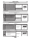
Table A.6 Wire Drive Interface Receptacle S6 (14 pin – MS
style)
Pin Function
A Motor "+"
B Motor "-"
C +40 VDC for solenoid
D Solenoid input
E Tach 2A differential signal
F Single Tach Input
G +15 VDC Tach
H Tach common
I Work voltage sense lead 21
J Electrode voltage sense lead 67
K Tach 1A differential signal
L Tach 1B differential signal
M Tach 2B differential signal
N Electrode voltage sense lead 67
1
2
3
4
5
6
7
8
9
10
11
12