


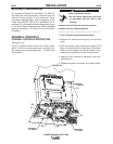
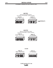
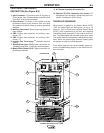
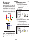
(See Figure B.5)
4. 10 Amp Wire Feeder Circuit Breaker: Protects 40
volt DC wire feeder power supply.
5. 115 VAC Auxiliary Power Circuit Breaker:
Protects case front receptacle auxiliary supply. (10
amps)
6. 21 Work Sense Lead Connector(4-Pin)
7. Arclink Connector (5-Pin)
8. DeviceNet Connector (5-Pin)
9. Work Output Studs
10. Electrode Output Studs
11. Auxiliary Output
12. Ethernet Connector (RJ-45)
13. Wire Feeder Connection (14-Pin)-Connects the
control cable between the power source and wire
feeder.
14. External Input Connector
15. Serial Communication (RS-232)
B-4
OPERATION
B-4
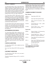
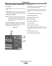
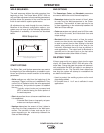
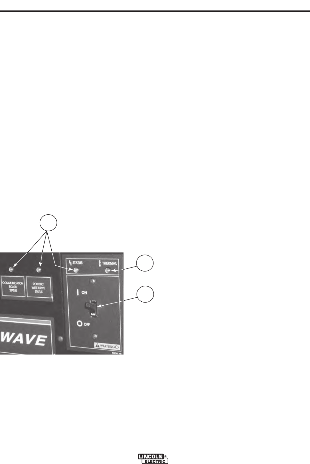
CASE FRONT CONTROL DESCRIPTIONS
(See Figure B.4)
1. Power Switch: Controls input power to the Power
Wave
2. Status Lights: A two color light that indicates sys-
tem errors. Normal operation is a steady green
light. Error conditions are indicated in the
Troubleshooting Section.
NOTE: The robotic PowerWaves’ status light will
flash green, for up to 15 seconds when the
machine is first turned on. This is a normal sit-
uation as the machine goes through a self
test at power up.
3. Thermal Fault Light : A yellow light that comes on
when an over temperature situation occurs. Output is
disabled until the machine cools down. When cool,
the light goes out and output is enabled.
FIGURE B.4
POWER WAVE® AC/DC 1000
2
3
1