


E-10
TROUBLESHOOTING
E-10
POWER WAVE® AC/DC 1000
Observe all Safety Guidelines detailed throughout this manual
If for any reason you do not understand the test procedures or are unable to perform the tests/repairs safely, contact your
Local Lincoln Authorized Field Service Facility for technical troubleshooting assistance before you proceed.
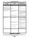
CAUTION
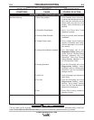
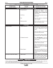
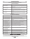
PROBLEMS
(SYMPTOMS)
POSSIBLE
CAUSE
RECOMMENDED
COURSE OF ACTION
Bad Weld Ending
Bad Welding
1. Burnback Disabled.
2. Burnback Time.
3. Analog Scans Between Updates.
4. Limit Error reported at the end of a weld.
5. Fan Out.
6. Welding set points.
7. Analog Hysteresis.
8. Gas.
1. Analog Scans Between Updates.
2. Voltage Sense Leads.
1. From the DeviceNet tab of the
Diagnostics Utility, select Monitor. The
Monitor window will be displayed. Verify
under the "State Enabled" that "Burnback"
is present.
2. Using Command Center verify that
Burnback Time for the active schedule in
the main window has a value other than 0.
3. The DeviceNet tab of the Diagnostics
Utility displays the Power Wave’s "Analog
Scans Between Updates" and "I/O
Scans/Sec." Verify that "Analog Scans
Between Updates" is 1/4 of "I/O
Scans/Sec" value.
4. Verify all welding settings for Burnback
and Crater states.
5. From the DeviceNet tab of the
Diagnostics Utility, select Monitor. Verify
under "Analog Input Fan Out" that
Burnback is present for all analogs in.
6. Verify Burnback set points for work point,
trim, and wave values.
7. From the DeviceNet tab of the
Diagnostics Utility, select Configure.
Verify in "Analog Input Channels" that the
Hysteresis settings are all 0.
8. Verify Gas is turned on.
1. The DeviceNet tab of the Diagnostics
Utility displays the Power Wave’s "Analog
Scans Between Updates" and "I/O
Scans/Sec." Verify that "Analog Scans
Between Updates" is 1/4 of "I/O
Scans/Sec" value.
2. Verify voltage sense leads are properly
connected and configured as described in
the instruction manual.
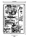
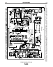
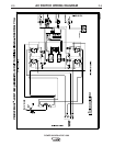
DEVICENET-PLC CONTROLLED SYSTEM