


B-6
OPERATION
B-6
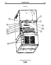
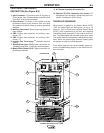
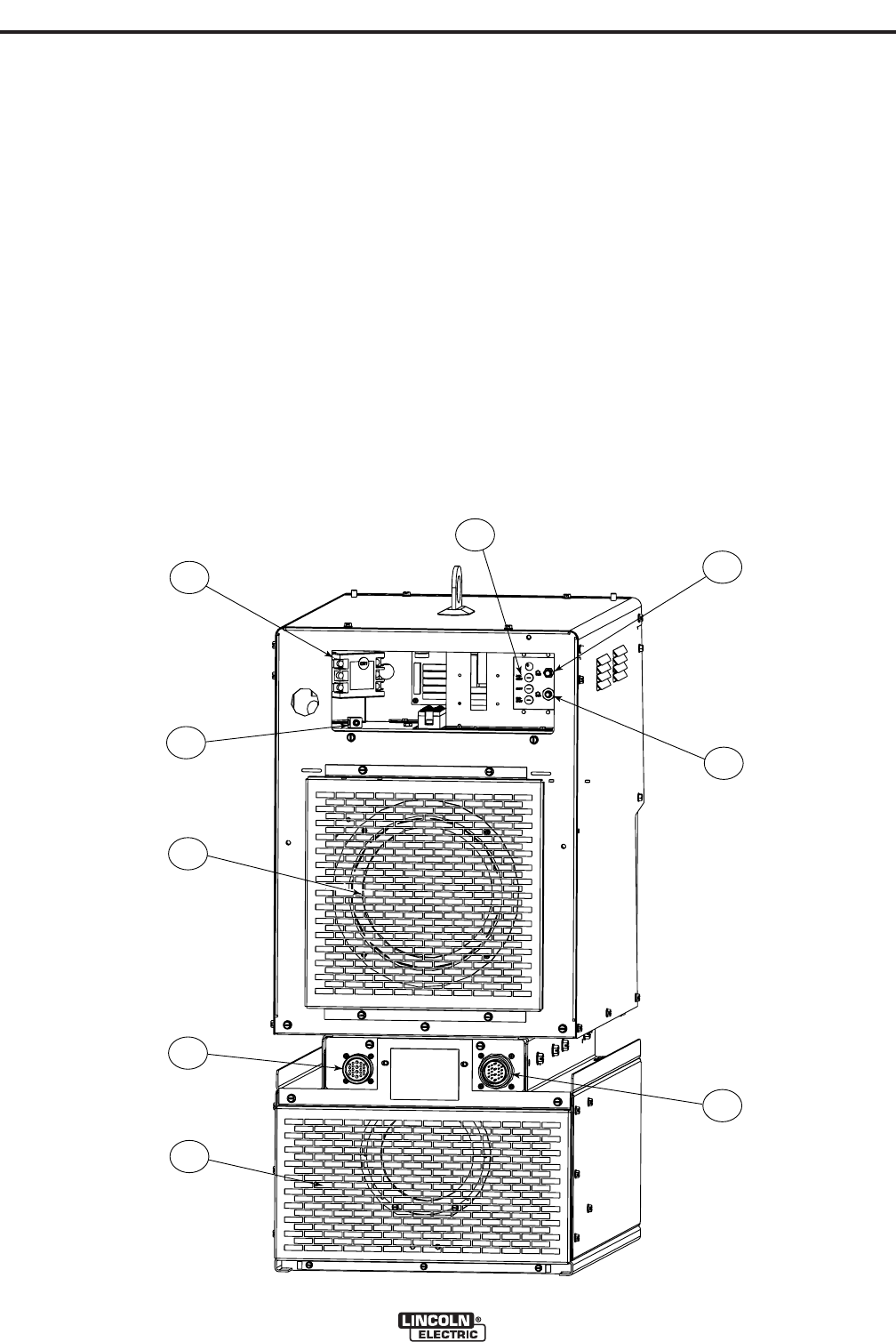
9. AC Switch Assembly W/Impeller Fan
10. Optional CE Filter Assembly (not shown): CE
compliance filter connects in series with input con-
nection. Available for K2344-2 only.
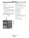
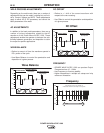
POWER-UP SEQUENCE
When power is applied to the Power Wave AC/DC
1000, the status lights will flash green, for up to 15
seconds. This is normal and indicates Power Wave
AC/DC 1000 is performing a self test, and mapping
(identifying) each component in the local ArcLink sys-
tem. The status lights will also flash green as a result
of a system reset or configuration change during oper-
ation. When the status lights become steady green
the system is ready for normal operation.
If the status lights do not become steady green con-
sult the troubleshooting section of this manual for fur-
ther instruction.
POWER WAVE® AC/DC 1000
1
2
9
8
3
4
5
7
6
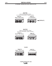
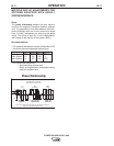
FIGURE B.6
CASE REAR COMPONENTS
DESCRIPTION (See Figure B.6)
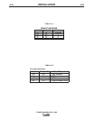
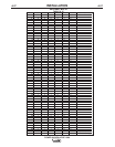
1. Input Contactor: Connection point for incoming 3
Phase power (see "Recommended Input Wire and
Fuse Size" chart in this document).
2. Case Ground: The frame of the welder must be
grounded to earth at this terminal. See your local
and national electrical codes for proper grounding
methods.
3. Auxiliary Reconnect: Select proper tap based on
input voltage.
4. CB3: Primary side protection for auxiliary trans-
former (T2).
5. CB4: Primary side protection for auxiliary trans-
former (T1).
6. Impeller Fan Technology
TM
provides superior
cooling.
7. Master/Slave Input (S12): Input connection for
paralleling machines, or multi-arc synchronization.
8. Master/Slave Output (S13): Output connection for
paralleling machines.