


A-19
INSTALLATION
POWER WAVE® AC/DC 1000
A-19
CONTROL CABLE CONNECTIONS
General Guidelines
Genuine Lincoln control cables should be used at
all times (except where noted otherwise). Lincoln
cables are specifically designed for the communica-
tion and power needs of the Power Wave / Power
Feed systems. Most are designed to be connected
end to end for ease of extension. However, it is rec-
ommended that the total length not exceed 100 feet
(30.5 m). The use of non-standard cables, especially
in lengths greater than 25 feet, can lead to communi-
cation problems (system shutdowns), poor motor
acceleration (poor arc starting), and low wire driving
force (wire feeding problems). Always use the shortest
length of control cable possible, and DO NOT coil
excess cable.
Regarding cable placement, best results will be
obtained when control cables are routed separate
from the weld cables. This minimizes the possibility of
interference between the high currents flowing
through the weld cables, and the low level signals in
the control cables. These recommendations apply to
all communication cables including optional DeviceNet
and Ethernet connections.
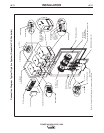
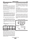
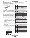
COMMON EQUIPMENT CONNECTIONS
Connection Between Power Source and Power
Feed 10S Series Wire feeder (K1785 - Control
Cable). The 14-pin wire feeder control cable connects
the power source to the wire drive. If there is more
than one power source per arc, it connects from the
wire drive to the power source designated as the
Master. It contains all of the necessary signals to drive
the motor and monitor the arc, including the motor
power, tachometer, and arc voltage feedback signals.
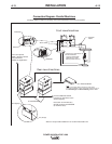
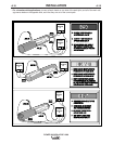
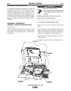
The wire feeder connection on the Power Wave
AC/DC 1000 is located under the spring loaded output
cover on the case front. The control cable is keyed
and polarized to prevent improper connection. For
convenience, the control cables can be routed along
the right channel of the Power Wave, out the back,
and to the wire feeder. Control cables SHOULD NOT
be routed through the same (left) channel as the weld-
ing cables.
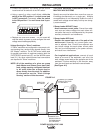
Connection Between Power Source and Power
Feed 10A Controller (K1543 – ArcLink Control
Cable). Single and tandem arc systems are typically
controlled by a Power Feed 10A Controller (K2362-1).
In a tandem, or multi-arc system, each arc requires its
own dedicated Power Feed 10A (PF-10A).
The 5-pin ArcLink control cable connects the power
source to the PF-10A. If there is more than one power
source per arc, it connects from the PF-10A to the
power source designated as the Master for that arc.
The control cable consists of two power leads, one
twisted pair for digital communication, and one lead
for voltage sensing. The ArcLink connection on the
Power Wave AC/DC 1000 is located under the spring
loaded output cover on the case front. The control
cable is keyed and polarized to prevent improper con-
nection. For convenience, the control cables can be
routed along the right channel of the Power Wave, out
the back, and to the PF-10A. Control cables SHOULD
NOT be routed through the same (left) channel as the
welding cables.
In multiple arc systems equipped with a Power Wave
System Interface (K2282-1), and controlled by PF-10A
controllers, the system interface must be connected to
the ArcLink network of the ARC1 Master power
source. See the "Tandem Arc Connection Diagram"
for detailed information.
Connections Between Power Source and Optional
DeviceNet Programmable Logic Controller(PLC). It
is sometimes more practical and cost effective to use
a custom PLC interface to control a multi-arc system
(refer to the "DeviceNet Configuration" section for
interface information). The Power Wave AC/DC 1000
is equipped with a 5-pin DeviceNet mini style recepta-
cle for this purpose. The receptacle is located under
the spring loaded output cover on the case front. The
DeviceNet cable is keyed and polarized to prevent
improper connection. For convenience, it can be rout-
ed along the right channel of the Power Wave, and
out the back. DeviceNet cables SHOULD NOT be
routed through the same (left) channel as the welding
cables.
In a typical system, a DeviceNet connection is made
between the master power source of each arc, and
the PLC interface. When a Power Wave System
Interface (K2282-1) is used to synchronize the arcs, it
must also be connected to the DeviceNet network. For
best results, route DeviceNet cables away from weld
cables, wire drive control cables, or any other current
carrying device that can create a fluctuating magnetic
field. DeviceNet cables must be sourced locally by the
customer. For additional guidelines refer to the
"DeviceNet Cable Planning and Installation Manual"
(Allen Bradley publication DN-6.7.2).