


A-23
INSTALLATION
POWER WAVE® AC/DC 1000
A-23
WIRE DRIVE GEAR RATIO SETTING
Changing the wirefeeder gear ratio requires a gear
change in the wire drive, and a configuration change
at the power source. The Power Wave AC/DC 1000
can be configured to support up to 4 unique gear
ratios. The gear ratio configuration is selected via a
DIP switch on the Feed Head PC Board and a jumper
on the External I/O connector (S7 - located beneath
the spring loaded output cover on the top, front of the
machine).
As shipped from the factory, the low speed (high
torque) gear is installed. To change the gear ratio of
the feeder, see the Wirefeeder Instruction Manual. To
achieve the correct speed, the power source must
also be configured for the actual gear ratio installed in
the wire drive per the instructions below:
ELECTRIC SHOCK can kill.
• Do not touch electrically live parts
or electrodes with your skin or wet
clothing.
• Insulate yourself from the work and
ground.
• Always wear dry insulating gloves.
-----------------------------------------------------------
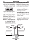
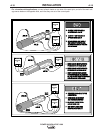
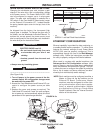
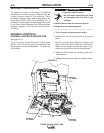
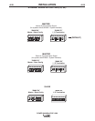
(See Figure A.3a)
1. Turn off power to the power source at the dis-
connect switch. All configuration changes must
be made with the power OFF.
2. Access the Feed Head board and External I/O con-
nector to configure the power source per table
A.9a.
3. Replace the cover and screws as required. The
Feed Head PC board will "read" the new configura-
tion at power up, and automatically adjust all control
parameters for the speed range selected.
WARNING
WARNING
S1S1
FEFEEEDHEDHEAADD
P.P.CC.. BOA BOARRDD
EXEXTTEERRNNAL I/OAL I/O
CCOONNNNEECTORCTOR
FIGURE A.3a
ETHERNET CONFIGURATION
Ethernet capability is provided for data monitoring, or
to enable parallel machine operation. To utilize these
features the network settings of each Power Wave
AC/DC 1000 must be properly configured. This is
accomplished through the use of the Weld Manager
software utility. Follow the instructions provided with
the utility to properly configure the Ethernet address.
When used in a system with parallel machines, the
Submerged Arc Cell Configuration software utility
must be used to map the master/slave relationships
within and between the different arc groups. This utili-
ty allows the user to configure the system by selecting
from a list of master and slave machines (as deter-
mined by their individual dip switch settings).
NOTE: Each machine must be configured as either a
Master or Slave via the dip switches on the
Ethernet PC Board. Furthermore, Master
machines must be configured for either inter-
nal synchronization (stand alone applica-
tions), or external synchronization (multiple
arc applications utilizing a Power Wave
System Interface). See the "Internal Controls"
section of this document.
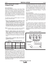
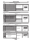
Ratio
142:1
95:1
57:1*
Reserved*
(Presently57:1)
Dip Switch #8
(Feed Head PCB - Bank S1)
OFF
ON
OFF
ON
External I/O Jumper
(Pin 5 to Pin 12)
NO
NO
YES
YES
* These Gear Ratios options are enabled in
S25564-11 and later Feed Head software.
TABLE A.9a
1
2
3
4
5
6
7
8
9
10
11
12
JUMPER PIN 5
J
UMPER PIN 12