


A-13
INSTALLATION
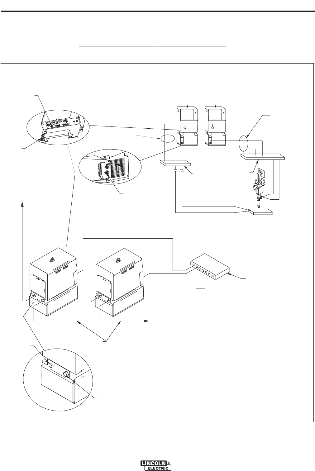
POWER WAVE® AC/DC 1000
A-13
MM
AA
SS
TT
EE
RR
SS
LL
AA
VV
EE
K
179
5-XX C
ables
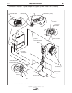
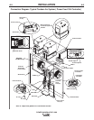
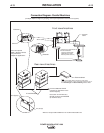
Connection Diagram - Parallel
Machines
(Example depicts a single arc grouping, and may be repeated for each arc in the system)
Connect additional
SLAVE
machines as required to reach
desired capacity.
Note: Each arc is limited to 5
SLAVE machines per MASTER
(6 machines total)
S
12 (Input)
S13 (Output)
Connect to optional
K2282-1 System Interface
for Synchronized
Multiple Arc Applications
E
thernet
Note:
Ethernet connectivity allows machines to share critical
parameter information. Proper configuration requires the use of
the
Weld Manager and
SubarcCellConfig
software utilities.
C
ommon bus connections
recommended for
excessive cable length
applications. (Locate
close to power sources.)
*
Electrode
Cables
* Work Cables
Work
E
lectrode
Front view o
f
machines
Rea
r view of machines
* Refer to "Output Cable Guidelines" for recommended cable size.
Ethernet S
witch