


A-15
INSTALLATION
POWER WAVE® AC/DC 1000
A-15
ELECTRODE AND WORK
CONNECTIONS
General Guidelines
The unique switching structure of the Power Wave
AC/DC 1000 allows it to produce DC positive, DC
negative or AC output waveforms without reposition-
ing the work and electrode leads. Additionally, no DIP
switch changes are required to switch between the dif-
ferent polarities. All of this is controlled internally by
the Power Wave AC/DC 1000, and based exclusively
on the weld mode selection.
The following recommendations apply to all output
polarities and weld modes:
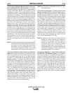
• Select the appropriate size cables per the
"Output Cable Guidelines" below. Excessive volt-
age drops caused by undersized welding cables
and poor connections often result in unsatisfactory
welding performance. Always use the largest weld-
ing cables (electrode and work) that are practical,
and be sure all connections are clean and tight.
Note: Excessive heat in the weld circuit indicates
undersized cables and/or bad connections.
• Route all cables directly to the work and wire
feeder, avoid excessive lengths and do not coil
excess cable. Route the electrode and work cables
in close proximity to one another to minimize the
loop area and therefore the inductance of the weld
circuit.
• Always weld in a direction away from the work
(ground) connection.
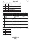
TABLE A.1 - Output Cable Guidelines
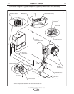
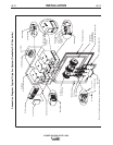
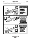
Electrode Connections
Connect an electrode cable of sufficient size and
length (Per Table A.1) to the "electrode" stud on the
power source (located behind the cover plate on the
lower left side). For convenience, the cable can be
routed down through the two holes in the left cable
tray before being connected to the output terminals.
Connect the other end of the electrode cable to the
wire drive feed plate on the wire feeder. Be sure the
connection to the feed plate makes tight metal-to-
metal electrical contact.
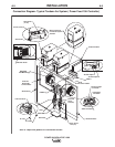
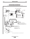
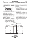
For parallel applications with excessive electrode
cable lengths, a common bus connection should be
used. The common electrode connection serves to
minimize voltage drops associated with resistive loss-
es in the electrode path. It should be made of copper,
and located as close as possible to the power
sources. (See "Connection Diagram – Parallel
Machines")
Work Connections
Connect a work lead of sufficient size and length (Per
Table 1) between the "work" stud (located beneath the
spring loaded output cover on the top, front of the
machine) and the work piece. For convenience, the
work lead can be routed along the left cable tray, and
out the back of the machine. Be sure the connection
to the work makes tight metal-to-metal electrical con-
tact.
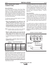
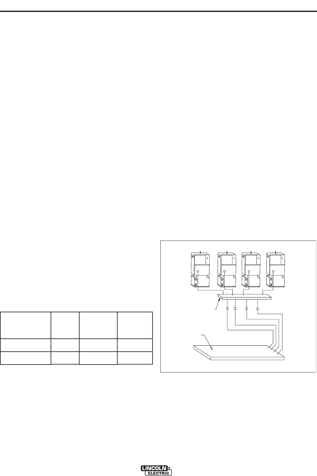
For parallel and/or multiple arc applications with
excessive ground path lengths, a common work con-
nection bus should be used. The common work con-
nection serves to minimize voltage drops associated
with resistive losses in the ground paths. It should be
made out of copper, and located as close as possible
to the power sources (See Common Connection
Diagram).
Total Cable Length
ft (m)
Electrode and Work
Combined
0 (0) to 250 (76.2)
0 (0) to 250 (76.2)
Duty Cycle
80%
100%
Number of
Parallel Cables
2
3
Cable Size
Copper
4/0 (120 mm
2
)
3/0 (95 mm
2
)
WORK PIECE
COMMON CONNECTION
(LOCATE
D
CLOSE TO
POWER SOUR
CES)
Common Connection Diagram