


A-20
INSTALLATION
POWER WAVE® AC/DC 1000
A-20
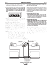
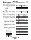
Connections Between Multiple Power Sources
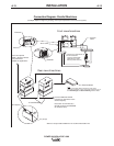
Run in Parallel (K1795 - Control Cable). To increase
the output capacity for a given arc, the output studs of
multiple Power Wave AC/DC 1000 machines can be
connected in parallel. The parallel machines utilize a
master/slave control scheme to distribute the load and
coordinate AC switching. The 22 pin parallel control
cable contains all of the necessary signals to keep the
machine outputs synchronized, including polarity,
ready, kill, and arc voltage feedback signals. The
cable connects between the Master/Slave I/O connec-
tors (S12 & S13) located on the rear of the Power
Wave AC/DC 1000. The input connector (S12) is
located on the lower left side of the case back (as
viewed from the rear), and the output connector (S13)
is located on the lower right side. The output connec-
tor (S13) on the master connects to the input connec-
tor (S12) on the slave. If needed the output connector
on the slave machine can be used to connect to the
input connector of another slave machine in a daisy
chain fashion. This connection scheme can be repeat-
ed as required until the desired output capacity is
achieved. The system is currently limited to a maxi-
mum of 5 slaves per master, or a total of 6 machines
per arc.
NOTE: In addition to the parallel control cable, parallel
connected machines also require an Ethernet
connection to share critical weld parameter
information. For more information refer to the
"Connections Between a Power Source and
Ethernet Network" section of this document.
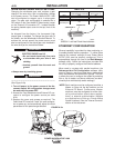
Connection Between Power Source and Ethernet
Network. Ethernet connections are required for sys-
tems with parallel connected power sources (more
than one power source per arc), or to utilize the tools
provided in the Power Wave Submerged Arc Utilities
software package. To facilitate this, the Power Wave
AC/DC 1000 is equipped with an RJ-45 Ethernet con-
nector, which is located under the spring loaded out-
put cover. External Ethernet equipment (cables,
switches, etc.) must be supplied by the customer. It is
critical that all Ethernet cables external to either a con-
duit or an enclosure are solid conductor, shielded cat
5 cable, with a drain. The drain should be grounded
at the source. The use of cat 5+, cat 5E, cat 6 or
stranded cable is not recommended. For best results,
route Ethernet cables away from weld cables, wire
drive control cables, or any other current carrying
device that can create a fluctuating magnetic field. For
additional guidelines refer to ISO/IEC 11801. Failure
to follow these recommendations can result in an
Ethernet connection failure during welding.
NOTE: See Ethernet Configuration section for addi-
tional information.
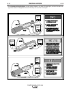
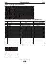
Connections Between a Power Source and
System Interface (K1795 - Control Cable). When
multiple arcs need to be synchronized, a Power Wave
System Interface (K2282-1) is required. The system
interface provides a dedicated synchronization signal
for frequency and balance to each of the four ARC
(a.k.a. PHASE) receptacles. The synchronization sig-
nals for ARC1 through ARC4 can be phase shifted
with respect to one another to reduce the effects of
"arc blow" and other welding related issues. The indi-
vidual synchronization signals are relayed to the mas-
ter machine of their corresponding arc via a 22 pin
control cable. The control cable(s) connect between
the individual ARC receptacles on the system inter-
face, and the Master/Slave input connector on the
master of each corresponding arc group. The
Master/Slave input connector (S12) is located on the
lower left side of the case back (as viewed from the
rear) of the Power Wave AC/DC 1000.
NOTE: In addition to the 22-pin arc synchronization
cables, the system interface also requires a
connection to the system controller either via
ArcLink for Power Feed 10A controlled sys-
tems (see "Connection Between Power
Source and Power Feed 10A Controller" ), or
via DeviceNet for PLC controlled systems (see
"Connection Between a Power Source and
Optional DeviceNet PLC Controller").
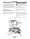
Connections Between a Power Source and Local
PC (RS-232 – Null Modem Cable). For diagnostic
and set up purposes it is sometimes necessary to
connect the power source directly to a PC (personal
computer). The Power Wave AC/DC 1000 is equipped
with an RS-232 DB-25 style serial connector for this
purpose. It is located under the spring loaded output
cover on the case front. RS-232 cables must be sup-
plied by the user (Radio Shack part # 26-269; Note:
USB port adapter - part #26-183 - is also required for
PC’s equipped with USB instead of a serial port). For
best results, route the RS-232 cable away from weld
cables, wire drive control cables, or any other current
carrying device that can create a fluctuating magnetic
field.