


A-17
INSTALLATION
POWER WAVE® AC/DC 1000
A-17
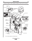
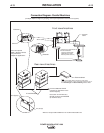
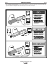
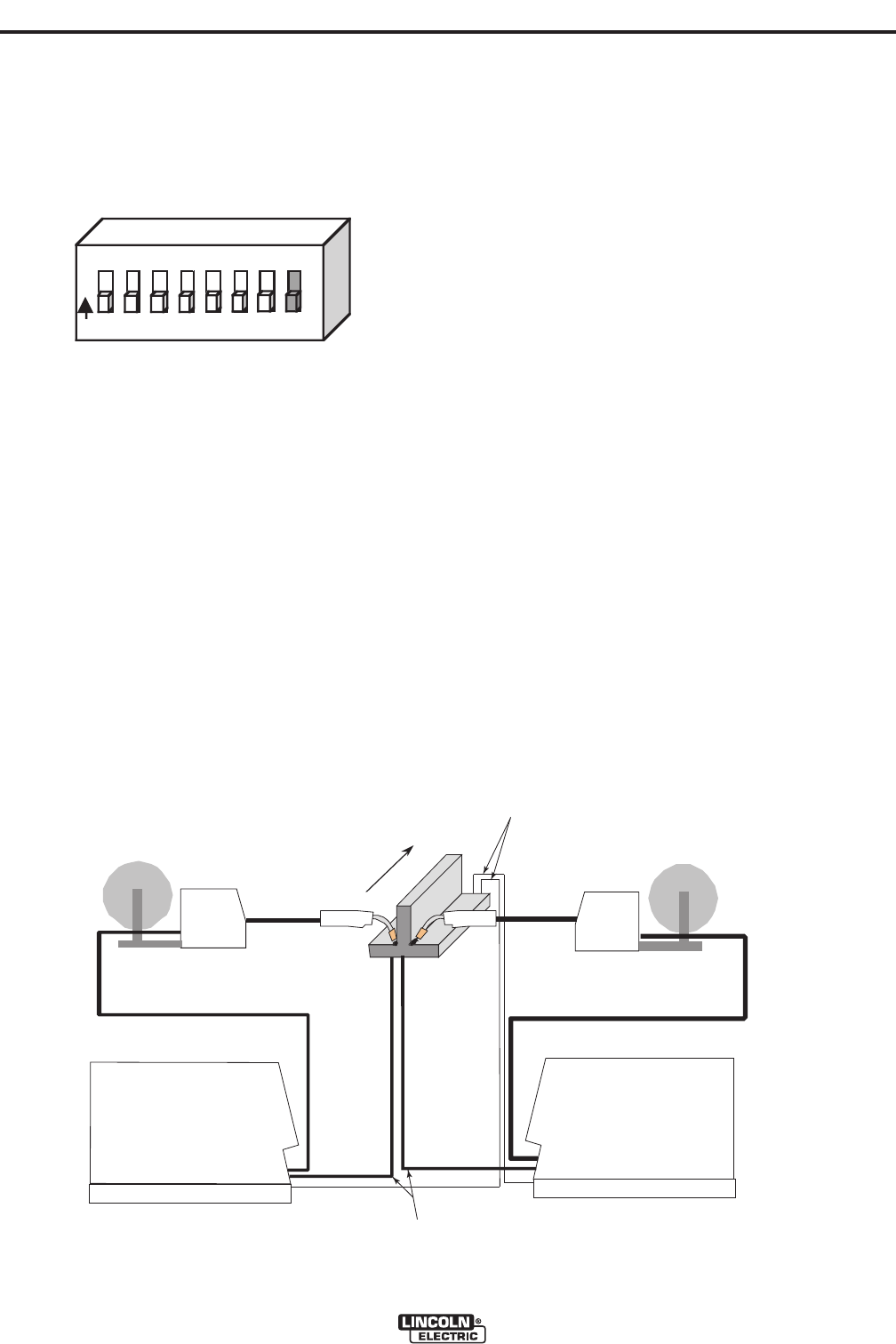
c. Locate the 8-position DIP switch on the control
board and look for switch 8 of the DIP switch.
d. Using a pencil or other small object, slide the
switch to the OFF position if the work sense lead
is NOT connected. Conversely, slide the switch
to the ON position if the work sense lead is pre-
sent.
e. Replace the cover and screws. The PC board will
read the switch at power up, and configure the work
voltage sense lead appropriately.
Voltage Sensing for "Slave" machines
If "Slave" machines are configured to use remote volt-
age sensing they receive these signals directly from
the "Master" machine. The K1795 control cable used
for parallel connection of machines contains both the
ELECTRODE sense lead (67) and the WORK sense
lead (21). No other external sense lead connections
are required for "Slave" machines.
NOTE: All of the machines of a given arc group
(both Master and Slaves) must have their
work voltage sensing configured identical-
ly. All must either use a remote lead or
sense directly from the stud. For addition-
al information see the "Work Voltage
Sensing" section of this document.
VOLTAGE SENSING CONSIDERATIONS FOR
MULTIPLE ARC SYSTEMS
Special care must be taken when more than one arc
is welding simultaneously on a single part. Multiple
arc applications do not necessarily dictate the use of
remote work voltage sense leads, but they are strong-
ly recommended.
If Sense Leads ARE NOT Used:
• Avoid common current paths. Current from adja-
cent arcs can induce voltage into each others cur-
rent paths that can be misinterpreted by the power
sources, and result in arc interference.
If Sense Leads ARE Used:
• Position the sense leads out of the path of the
weld current. Especially any current paths com-
mon to adjacent arcs. Current from adjacent arcs
can induce voltage into each others current paths
that can be misinterpreted by the power sources,
and result in arc interference.
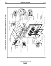
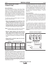
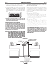
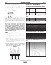
• For longitudinal applications, connect all work
leads at one end of the weldment, and all of the
work voltage sense leads at the opposite end of the
weldment. Perform welding in the direction away
from the work leads and toward the sense leads.
(See Figure A.2)
1 2 3 4 5 6 7 8
O
N
DIRECTION
OF TRAVEL
CONNECT ALL
WORK LEADS AT
THE BEGINNING
OF THE WELD.
CONNECT ALL SENSE
LEADS AT THE END
OF THE WELD.
FIGURE A.2