


A-5
INSTALLATION
A-5
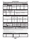
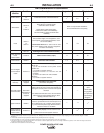
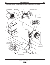
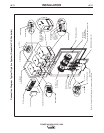
RECOMMENDED EQUIPMENT
System
Identifier
Power Source
Weld Cables
Head
Torch
Power Source to
Head
Control Cable
User Interface
ArcLink Digital
Communication
Cable
PLC (w/ User
Interface)
DeviceNet Cables
and Accessories
System Interface
System Interface
to Power Source
Control Cable
Part No.
K2344-1
-or-
K2344-2
K2163-xx
-or-
K1842-xx
K2370-1
-or-
K2312-1
K231-xxx
K1785-xx
K2362-1
K1543-xx 5
Customer
Supplied
Automation
Department or
Customer
Supplied
K2282-1
K1795-xx 5
Single Arc
4
1
1
1
2
1
1
2
1
2,4
1
---
---
---
---
Tandem Arc
4
2
1
2
2
2
2
2
2
2,4
3
---
---
1
2
2
2
Description
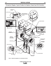
Power Wave AC/DC 1000 Power Source
Welding Power Cables
Power Source to contact Nozzle,
and Power Source to Work
K2163 Series cables sold in pairs.
K1842 Series cables sold individually.
See Price Book for details and bulk cable
availability.
Power Feed 10S Head for 3/32 to 7/32 in. solid
wire (includes hopper, wire straightener, cross
seam adjuster, head mounting hardware, and 2 -
5ft 4/0 weld cables).
Power Feed 10S Head for 3/32 to 7/32 in. solid
wire (fixture builder's head, with wire straightener -
insulators not included).
Submerged Arc Contact Nozzle Assembly
Feeder Control Cable (14 pin).
Power Feed 10A Controller
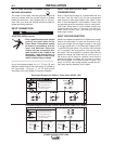
ArcLink Control Cables (5 pin).
Single Arc:
(1) PF-10A Controller to the power source
Tandem Arc:
(1) Lead Arc to System Interface
(2)System Interface to Lead Arc PF-10A
Controller
(3) Trail Arc to Trail Arc PF-10A Controller
Triple Arc:
(1) Lead Arc to System Interface
Programmable Logic Controller
(DeviceNet compatible)
DeviceNet Cables, Tees, and Terminators (5 pin)
sealed "mini style") form a trunk style network con-
necting PLC to each power source and the System
Interface.
For additional information refer to the "DeviceNet
Cable Planning and Installation Manual" (Allen
Bradley publication DN-6.7.2).
Power Wave System Interface provides the
means to synchronize the AC wave shapes of up
to four different arcs to a common carrier frequen-
cy, and control the phase angle between them to
reduce the effects of "Arc Blow".
Control Cable (22 pin) connects between each
power source and the System Interface.
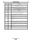
Triple Arc
3,4
3
1
3
2
3
3
2
---
1
1
4
Cables, Tees,
and
Terminators
as required
per Triple Arc
Connection
Diagram
4
1
2
3
2
Refer to "Output Cable Guidelines"
for recommended size and quantity
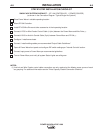
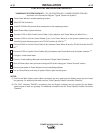
Notes:
1. "Recommended Quantity" assumes one power source per arc. Multiple power sources may be used to increase the output capacity per arc (see "Connection Diagram - Parallel
Machines").
2. Control Cable connections only required at the Master of each parallel power source arc grouping.
3. Can be expanded to 4 or more arcs (Note: The System Interface can currently only synchronize up to four AC arc groupings).
4. The triple arc system is an economical breakpoint for a PLC Interface. It does not preclude the use of a PLC for single or tandem arc systems, nor PF-10A's from being used to control
multiple arc systems with greater than two arcs.
5. Cables can be connected end to end to extend length.
POWER WAVE® AC/DC 1000