


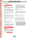
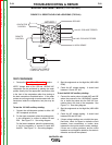
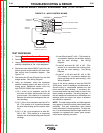
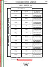
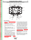
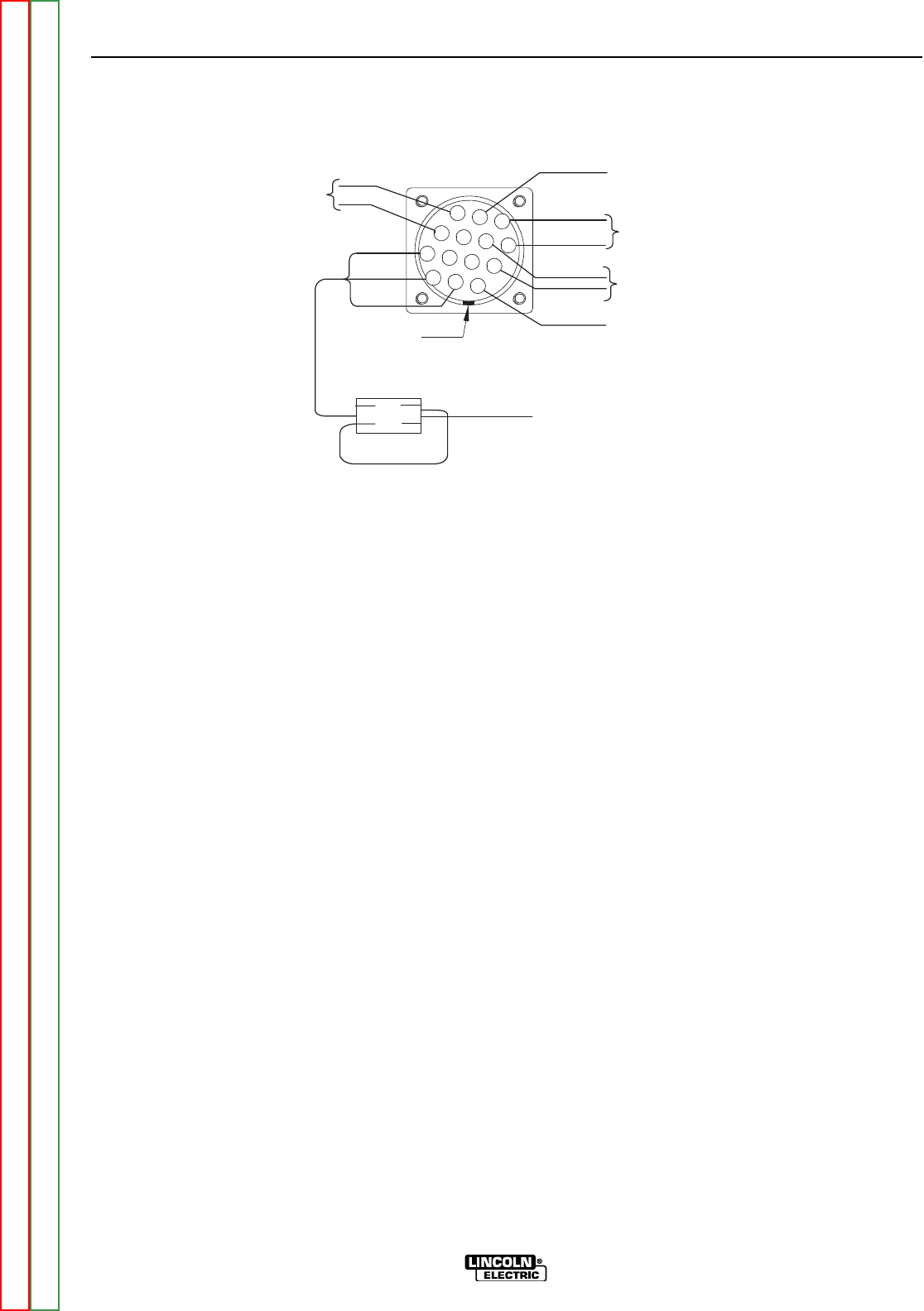
FIGURE F.13 - WELD CONTROL BOARD
STATOR SHORT CIRCUIT & GROUND TEST (CONTINUED)
TEST PROCEDURE
1. Perform Case Cover Removal Procedure.
2. Perform Capacitor Discharge Procedure.
3. Unplug anything that may be connected to the
auxiliary receptacles or the 14 pin amphenol.
4. Disconnect and isolate GND-E lead from the
bottom ground screw inside the left case front.
See control Inner-Connection diagram. See
Figure F.13.
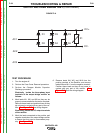
5. Disconnect the #5 and #6 leads from the field
bridge rectifier. See Wiring Diagram.
6. Using an ohmmeter, check the resistance
between chassis ground and each of the fol-
lowing points; Resistance should read very
high, 500,000 (500K) ohms minimum.
1) Pin 1 at the 14 pin amphenol, and the #5
lead that had been disconnected from the
ground screw. (this checks for a connection
between the wire feed winding and the aux-
iliary winding.)
2) Pin 1 of the 14 pin amphenol and lead #7 or
#9. (This checks for a connection between
the wire feed winding and the exciter wind-
ing.)
3) Pin 1 of the 14 pin amphenol an lead W1,
W2, or W3. (This checks for a connection
between the wire feed winding and the weld
winding).
4) Lead #5 and lead #7 or #9. (This checks for
a connection between the auxiliary winding
and the weld winding). See Wiring
Diagram.
5) Lead #5 and lead W1, W2, or W3. (This
checks for a connection the auxiliary wind-
ing and the weld winding.) See Wiring
Diagram.
6) Lead #7 or #9 and lead W1, W2, or W3.
(This checks for a connection between the
exciter winding and the weld winding.) See
Wiring Diagram.
If any of the above readings is less than 500,000
(500k) ohms, check for damaged, contaminated, or
shorted wiring or components between the test
points and the stator winding. If necessary, dis-
connect and isolate the stator leads as close to the
stator winding as possible. See wiring diagram. If
the low resistance is determined to be between the
windings within the stator, the stator is defective
and should be replaced*.
NOTE: The field bridge rectifier and field capacitor
may appear to function normally when tested inde-
pendently. But may malfunctions when placed
under the stress of normal operation. For this rea-
son, It is recommended that the bridge rectifier and
capacitor be replaced with known good compo-
nents before replacing the stator.
TROUBLESHOOTING & REPAIR
F-56 F-56
VANTAGE® 400
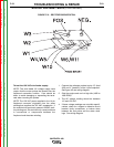
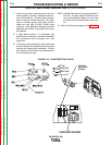
AMPHENOL 1
KEY
E
C
D
A
B
L
K
J
M
N
F
G
H
I
CONTACTOR
CONTROL
L4
GROUND
120 VAC FOR WIRE FEEDER
40 VAC FOR WIRE FEEDER
21 WORK SENSE
2 TIMES THRU FERRITE
LEADS 75A, 76A, & 77A
REMOTE
CONTROL
Return to Section TOC Return to Section TOC Return to Section TOC Return to Section TOC
Return to Master TOC Return to Master TOC Return to Master TOC Return to Master TOC