


{
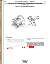
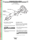
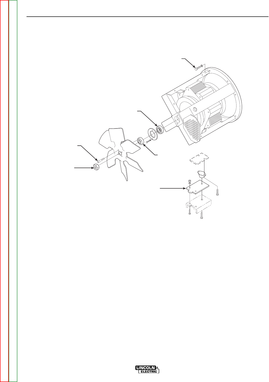
STATOR / ENGINE
MOUNTING BOLTS &
LOCK WASHERS (8)
BEARING
BOLTS (4)
FAN NUT
FAN HUB
MOUNTING
PLATE
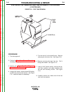
FIGURE F.24 – DOOR REMOVAL
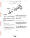
STATOR/ROTOR REMOVAL AND REPLACEMENT PROCEDURE
(CONTINUED)
STATOR REMOVAL PROCEDURE
1. Using a 1/2” wrench, remove the four fan blade
mounting bolts and lock washers. See Figure
F.24.
2. Using a 1 1/8” wrench, remove the fan nut.
Remove the fan, noting the direction for
reassembly.
3. Using the gear puller, remove the fan hub.
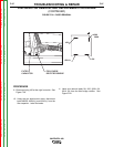
4. Using a 3/8” wrench, remove the two bolts and
flat washers holding the bearing in place.
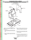
5. Using a 1/2” wrench, remove the two nuts, lock
washers, and carriage bolts holding the gener-
ator mounting plate to the machine base.
6. Support the stator with a hoist. Place wooden
blocks under the engine to support it when the
stator is removed.
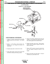
7. Using a 9/16” wrench, remove the eight bolts
and lock washers holding the stator to the
engine.
8. Remove the stator from the engine. It may be
necessary to pry and slide it free.
TROUBLESHOOTING & REPAIR
F-101 F-101
VANTAGE® 400
Return to Section TOC Return to Section TOC Return to Section TOC Return to Section TOC
Return to Master TOC Return to Master TOC Return to Master TOC Return to Master TOC