


THEORY OF OPERATION
E-3 E-3
VANTAGE® 400
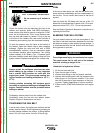
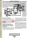
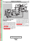
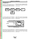
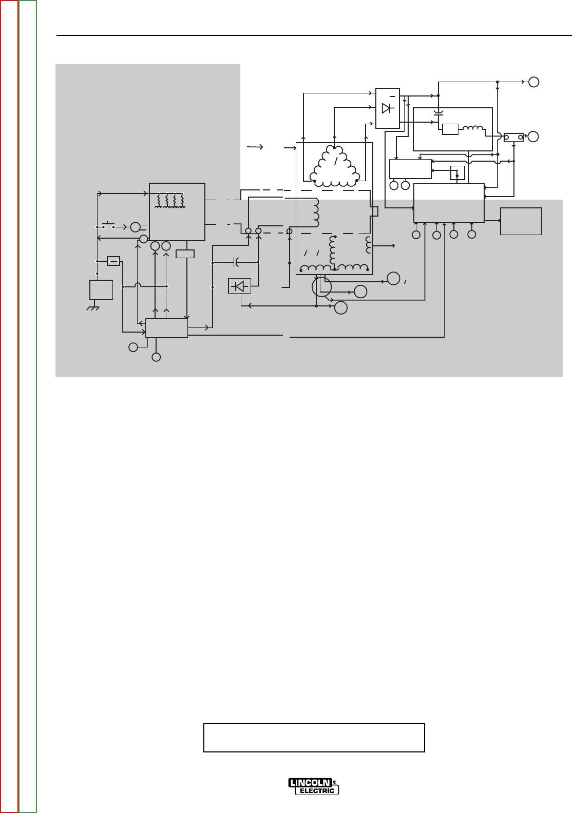
FIGURE E.3 — WELD WINDINGS, RECTIFIER, CHOPPER MODULES & FEEDBACK
W
E
L
D
W
I
N
D
I
N
G
30
AUXILIARY
WINDINGS
10 + 30
ROTOR
+
REMOTE
AMPHENOL
ARC
CONTROL
OUTPUT
CONTROL
PROCESS/RANGE
SELECTOR
WELD
CONTROL
BOARD
THREE-PHASE
RECTIFIER
WORK
TERMINAL
ELECTRODE
TERMINAL
CHOPPER MODULE
IGBT
CHOKE
VOLTMETER
AMMETER
PWM
SIGNAL
VRD
VOLTAGE REDUCTION
VRD FEEDBACK
VRD
LIGHTS
R
G
VRD
SWITCH
(OFF)
SHUNT
AUX. FEEDBACK
120VAC
RECEPTACLED (2)
AUX
CURRENT
TORROID
42 VAC TO 14 PIN AMPHENOL
FOR WIRE FEEDER
240 VAC
30
240VAC
RECEPTACLE
LOW IDLE COMMAND
F
E
E
D
B
A
C
K
C
U
R
R
E
N
T
I
D
L
E
V.R.D.
POWER TO CONTROL BOARD
POWER TO
VRD
80 VDC
VOLT
FEEDBACK
+
-
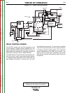
ENGINE
GLOW PLUGS
MECHANICAL
ROTATION
STARTER
ALTERNATOR
BATTERY
OIL PRESS
TEMP
ROTOR
FLASH
ENGINE PROTECTION
IDLER CONTROL
P.C. BOARD
STATOR
SLIP
RINGS
+
-
RUN/STOP
SWITCH (RUN)
ENGINE
SENSORS
ENGINE
TROUBLE
LIGHT
Y
ALT
SOL SOL
ALT FLASH
S
H
U
T
D
O
W
N
I
D
L
E
R
+
-
Y
ALTERNATOR
LIGHT
NOTE: Unshaded areas of Block Logic
Diagram are the subject of discussion
WELD WINDINGS, RECTIFIER,
POWER MODULES AND
FEEDBACK
The three-phase stator weld windings are connected to
a three-phase rectifier bridge. The resultant DC voltage
is applied to four paralleled capacitors incorporated
within each of the two power modules. There are two
capacitors in each module. These capacitors function
as filters and also as power supplies for the IGBTs.
See IGBT Operation in this section. The IGBTs act as
high-speed switches operating at 20KHZ. These
devices are switched on and off by the Weld Control
PC board through pulse width modulation circuitry.
See Pulse Width Modulation in this section.
This "chopped" DC output is applied through choke
coils and a shunt to the welding output terminals. The
choke functions as a current filter, and it helps to bal-
ance the outputs of the two power modules. Free-
wheeling diodes are incorporated in the power mod-
ules to provide a current path for the stored energy in
the choke when the IGBTs are turned off. See
Chopper Technology in this section.
Output voltage and current feedback information is fed
to the Weld Control PC board. This information is
sensed from the output terminal circuits and the shunt.
Return to Section TOC Return to Section TOC Return to Section TOC Return to Section TOC
Return to Master TOC Return to Master TOC Return to Master TOC Return to Master TOC