


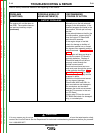
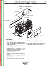


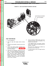
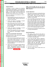
B1
B2
B3 B6
B5
B4
INSULATED
GLOVES
INSULATED
PLIERS
FIGURE F.2 - CHOPPER MODULE CAPACITOR TERMINAL DISCHARGE
CHOPPER MODULE CAPACITOR DISCHARGE PROCEDURE (CONTINUED)
TROUBLESHOOTING & REPAIR
F-26 F-26
VANTAGE® 400
ELECTRIC SHOCK can kill.
• Do not touch electrically hot parts.
• Prior to performing preventative
maintenance, perform the following
capacitor discharge procedure to
avoid electric shock.
DISCHARGE PROCEDURE
1. Turn the engine off.
2. Perform the Case Cover Removal procedure.
NOTE: It is necessary to remove the fuel cap in
order to take the case cover off the
machine. Be sure the fuel cap is ON when
discharging the chopper module capaci-
tors.
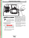
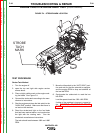
3. Locate the chopper module and capacitor
assembly on the inner machine baffle. See
Figure F.2 and the Wiring Diagram.
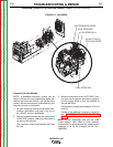
NEVER USE A SHORTING STRAP TO DIS-
CHARGE CAPACITORS. If the Lincoln recom-
mended resistor, or an equivalent resistor is used,
the capacitors can be discharged by holding the
resistor with insulated pliers and using the resistor
terminals to bridge Chopper Module terminals B1
to B2, and B4 to B5. DO NOT TOUCH THE TER-
MINALS OR METAL PARTS OF THE PLIERS
WITH YOUR BARE HANDS. Hold the resistor in
place for about 10 seconds.
If another type of resistor is used, jumper leads
may need to be attached to the resistor. The
leads can then be used to connect terminals
B1 to B2, and B4 to B5.
4. Using the volt/ohmmeter, check the voltage
across B1 and B2, then B4 and B5. It should
be zero volts in both cases.
WARNING
Return to Section TOC Return to Section TOC Return to Section TOC Return to Section TOC
Return to Master TOC Return to Master TOC Return to Master TOC Return to Master TOC