


ROTOR RESISTANCE AND GROUND TEST (DYNAMIC) (CONTINUED)
TEST PROCEDURE
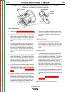
This test requires that the brushes and slip rings
are clean, in good condition, and are properly
seated.
1. Perform the brush and slip ring service
procedure if necessary.
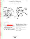
2. Insulate the lead wires that had been discon-
nected from the brushes during the static
rotor resistance test. Position and secure
them so they cannot become damaged by the
spinning rotor.
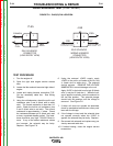
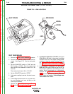
3. Securely attach the ohmmeter leads to the
brush terminals. Use clips or terminals to
attach the leads BEFORE starting the engine.
4. Start the engine and run it at high idle speed
(1860-1890 RPM). The resistance should
read approximately 25Ω at 77ºF (25º C.)
4. Shut off engine, and move one of the ohmme-
ter leads to a good clean chassis ground.
5. Restart the engine and run it at high idle
speed (1860-1890 RPM). The resistance
should be very high, at least 500,000 (500k)
ohms.
6. If the resistance readings differ significantly
from the values indicated, re-check the brush-
es and the brush spring tension. If the brush-
es and slip rings are good, replace the rotor.
7. If all testing is finished, perform the Case
Cover Replacement procedure.
*NOTE: The resistance of the windings will
change with temperature. Higher temperatures
will produce higher resistance, and lower temper-
atures will produce lower resistance.
TROUBLESHOOTING & REPAIR
F-42 F-42
VANTAGE® 400
Return to Section TOC Return to Section TOC Return to Section TOC Return to Section TOC
Return to Master TOC Return to Master TOC Return to Master TOC Return to Master TOC