


#201A-
5H
#200
200A
#6A
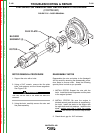
FILTER
CAPACITOR
FIELD DIODE
RECTIFIER BRIDGE
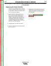
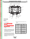
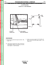
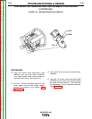
FIGURE F.20 – DOOR REMOVAL
STATOR/ROTOR REMOVAL AND REPLACEMENT PROCEDURE
(CONTINUED)
PROCEDURE
9. Disconnect plug J30 at the right front side. See
Figure F.20.
10. Using the slot head screw driver, disconnect
leads #200B, #200A(+) and #201A(-) from the
filter capacitor. Label the leads.
11. Label and remove leads 5H, 200, 200A, 6A,
201A, 5H from the field bridge rectifier. See
Figure F.20.
TROUBLESHOOTING & REPAIR
F-97 F-97
VANTAGE® 400
Return to Section TOC Return to Section TOC Return to Section TOC Return to Section TOC
Return to Master TOC Return to Master TOC Return to Master TOC Return to Master TOC