


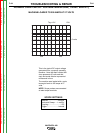
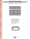
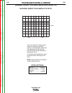
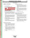
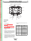

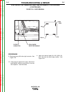
FIGURE F.18 - MODULE LEAD LOCATIONS
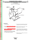
CHOPPER MODULE REMOVAL AND REPLACEMENT (CONTINUED)
PROCEDURE
REMOVAL
1. Turn the engine off.
2. Perform the Case Cover Removal
Procedure.
3. Perform the Chopper Module Capacitor
Discharge procedure.
4. Disconnect leads 23 and 25 at their in-line
couplings.
5. Using the 7/16” socket wrench, remove the fol-
lowing leads. Label the leads before removal.
Cut cable ties as needed. Note placement of
leads and fasteners: screw, lock washer, flat
washer, small lead, heavy lead.
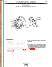
6. Using a 3/8” socket wrench, remove the three
screws holding the power module assembly to
its brackets on the vertical baffle. Remove the
plastic strip with the top two screws. Be sure
to support the Power Module as you remove
the last screw.
7. Remove the Power Module assembly from the
machine.
TROUBLESHOOTING & REPAIR
F-92 F-92
VANTAGE® 400
B1
B2
B3
B6
B5
B4
23
25
SL302
SL301
HL W9
HL W4
HL W6
SL14
SL13
B8
HL W8
HL W5
HL W11
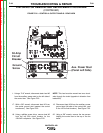
LED1LED1
LED4LED4
LED2LED2
LED3LED3
L12683-1
LED1 (B1,B2,B3)
Chopper Working
LED3 (B4,B5,B6)
Chopper Working
LED4
PWM Signal
LED2
Voltage from
Rectifier
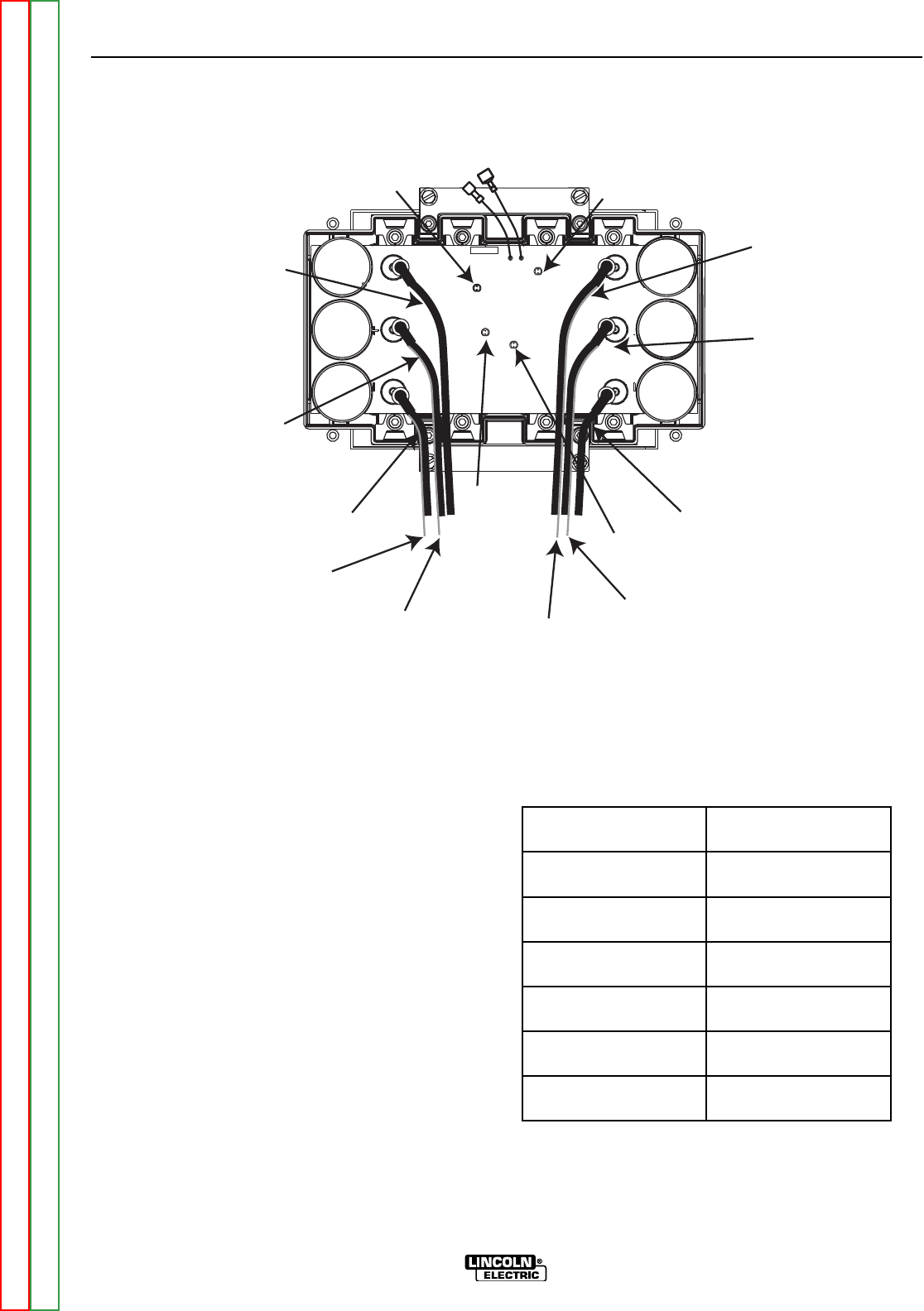
TERMINAL LEADS
B4
Heavy lead W11,
Small lead 14
B5
Heavy lead W5,
Small lead 13
B6
Heavy lead W8
B1
Heavy lead W6
B2
Heavy lead W4,
Small lead 301
B3
Heavy lead W9,
Small lead 302
Return to Section TOC Return to Section TOC Return to Section TOC Return to Section TOC
Return to Master TOC Return to Master TOC Return to Master TOC Return to Master TOC