


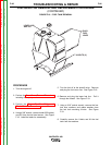
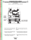
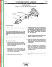
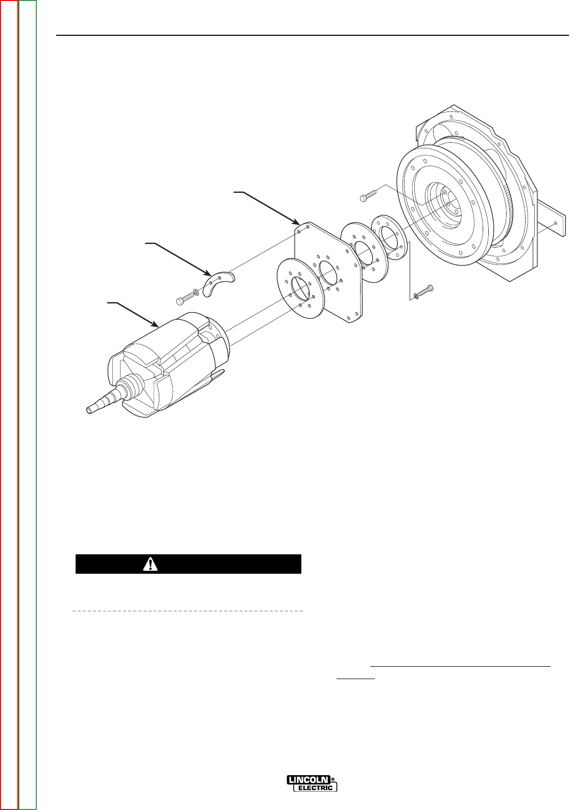
FLEX PLATE
BLOWER
SEGMENT (4)
ROTOR
FIGURE F.25 – DOOR REMOVAL
STATOR/ROTOR REMOVAL AND REPLACEMENT PROCEDURE
(CONTINUED)
TROUBLESHOOTING & REPAIR
F-102 F-102
VANTAGE® 400
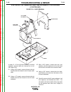
ROTOR REMOVAL PROCEDURE
1. Support the rotor with a hoist.
2. Using a 5/16” wrench, remove the flex plate
bolts, lock washers, and four blower segments.
See Figure F.25.
The rotor will be free to fall when the bolts are
removed.
3. Using the hoist, carefully remove the rotor and
flex plate assembly.
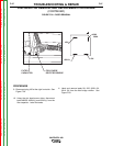
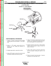
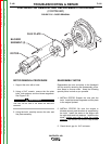
REASSEMBLY NOTES
Reassemble the rotor and stator to the Vantage®
400 by carefully retracting the disassembly proce-
dure steps in reverse order. Keep the following
special points in mind as you proceed.
1. INSTALL ROTOR: Support the rotor with the
hoist. Install the blower segments and flex plate
to the engine flywheel.
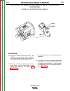
2. INSTALL STATOR: Be sure the engine is
blocked securely and the stator is supported by
the hoist. Install the stator to the engine with
the eight bolts and lock washers. Install the fan
blade, making sure that it faces the proper
direction, with the fan nut and four cap screws.
3. Check the air gap for .012” minimum.
WARNING
Return to Section TOC Return to Section TOC Return to Section TOC Return to Section TOC
Return to Master TOC Return to Master TOC Return to Master TOC Return to Master TOC