


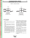
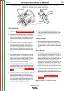
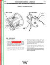

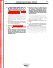

BRUSHES
SLIP RINGS
#200A
#200B
#201
-
+
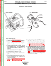
FIGURE F.9 - ROTOR BRUSH LEADS
ROTOR RESISTANCE AND GROUND TEST (STATIC) (CONTINUED)
TEST PROCEDURE
1. Turn the engine off.
2. Perform the Case Cover Removal procedure.
3. Locate and label the leads from the rotor brush
holder assembly. See Figure F.9. Using the
needle nose pliers, remove the leads. This will
electrically isolate the rotor windings.
4. Using the ohmmeter, check the rotor winding
resistance across the slip rings. See Figure
F.9. Normal resistance is approximately 25
ohm, at 77º F. (25º C.).
5. Measure the resistance to ground. Place one
meter probe on either of the slip rings. Place
the other probe on any good unpainted chassis
ground. The resistance should be very high, at
least 500,000 (500k) ohms.
6. If the test does not meet the resistance speci-
fications, then the rotor may be faulty and
should be replaced.
7. If this test meets the resistance specifications,
continue testing using the dynamic rotor resis-
tance and ground test.
TROUBLESHOOTING & REPAIR
F-40 F-40
VANTAGE® 400
Return to Section TOC Return to Section TOC Return to Section TOC Return to Section TOC
Return to Master TOC Return to Master TOC Return to Master TOC Return to Master TOC