


OUTPUT RECTIFIER BRIDGE AND CHOKE REMOVAL AND REPLACEMENT
(CONTINUED)
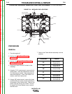
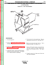
Replacing the Output Rectifier
1. Place the Output Rectifier into the machine
so that its mounting studs fit into the holes
in the bracket. Place a lock washer and a
nut on each stud and tighten.
2. Apply a thin film of electrical joint com-
pound, (Dow Corning) between the sur-
faces of the “W” leads and the Output
Rectifier. Reconnect the Output Rectifier,
positioning the leads, bolts, washers, and
nuts exactly as hey had been originally
connected. Tighten all of the connections
securely. See Wiring Diagram.
3. Swing the case front back into position.
4. Attach the case front to the machine base
with four screws.
5. Reconnect all of the leads and plugs that
were disconnected during the removal pro-
cedure, and replace any cable ties that
were removed.
6. Perform the Case Cover Removal
Procedure.
TROUBLESHOOTING & REPAIR
F-89 F-89
VANTAGE® 400
Return to Section TOC Return to Section TOC Return to Section TOC Return to Section TOC
Return to Master TOC Return to Master TOC Return to Master TOC Return to Master TOC