


CONTROL POTENTIOMETER AND MODE SWITCH RESISTANCE TEST
(CONTINUED)
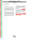
TEST PROCEDURE
1. Turn the engine off
2. Perform the Case cover Removal Procedure.
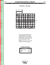
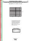
3. Unplug P7 from control board, see control
Inner-connection diagram, and visually check
the plug and attached wiring for damage, cor-
rosion, improperly seated or damaged contact
pins. P7 will remain unplugged for following
test.
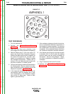
4. Set the mode switch in the “CC-Stick” position.
5. Test the resistance between each of the leads
in P7 and a good clean chassis ground con-
nection. Be very careful that the connection
pins in P7 are not damaged or spread out.
6. The resistance should be very high. A reading
of 500,000 (500k) ohms or higher is accept-
able.
7. If the resistance is lower than 500k Ohms,
replace the potentiometer and mode switch
plug and lead assembly, or replace the defec-
tive component within the assembly. See
wiring diagram.
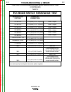
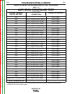
8. Perform the resistance tests per Table F.3.
9. If the resistance readings are not as specified
in the table, replace the potentiometer and
mode switch plug and lead assembly, or
replace the defective component. See the
wiring diagram.
10. If testing is complete, plug P7 back into the
control PC board and perform the Case Cover
Replacement procedure.
TROUBLESHOOTING & REPAIR
F-76 F-76
VANTAGE® 400
Return to Section TOC Return to Section TOC Return to Section TOC Return to Section TOC
Return to Master TOC Return to Master TOC Return to Master TOC Return to Master TOC