


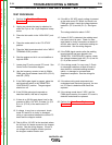


WELD CONTROL FEEDBACK TEST (CONTINUED)
16. If the voltage readings are different, check the
wiring and connections between the welding
terminals and the control PC board. See the
wiring diagram.
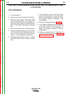
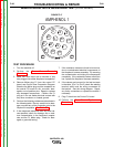
17. Connect the millivolt meter probes between
lead #206S+ (P6-2) and lead 204S- (P6-1).
See Wiring Diagram. If the machine is cur-
rently producing 200 amps the millivolt meter
should read about 25 millivolts.
18. If the machine cannot produce 200 amps of
weld current, the correct millivolt signal will
need to be calculated by dividing the reading
displayed on the external ammeter by 8. See
the following explanation.
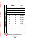
19. The shunt used in this machine will produce
50 millivolts at a load of 400 amps, or 8 amps
per millivolt.
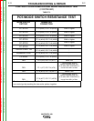
20. To calculate the correct millivolt signal for a
given load, you divide the number of amps
displayed on the ammeter by 8.
Example: If your ammeter reads 75, (75/8 =
9.4) If the shunt is working correctly, and the
wiring between the shunt and the control PC
board is in good condition, the meter connect-
ed at the control PC board should be reading
about 9.4 millivolts.
21. If the millivolt reading is incorrect, check the
wiring between the shunt and the control PC
board for damage, grounds, and faulty con-
nections. If the wiring is good, the shunt and
lead assembly is faulty and should be
replaced.
22. Perform the Case Cover Replacement
Procedure.
TROUBLESHOOTING & REPAIR
F-73 F-73
VANTAGE® 400
Return to Section TOC Return to Section TOC Return to Section TOC Return to Section TOC
Return to Master TOC Return to Master TOC Return to Master TOC Return to Master TOC