


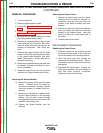
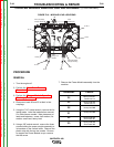

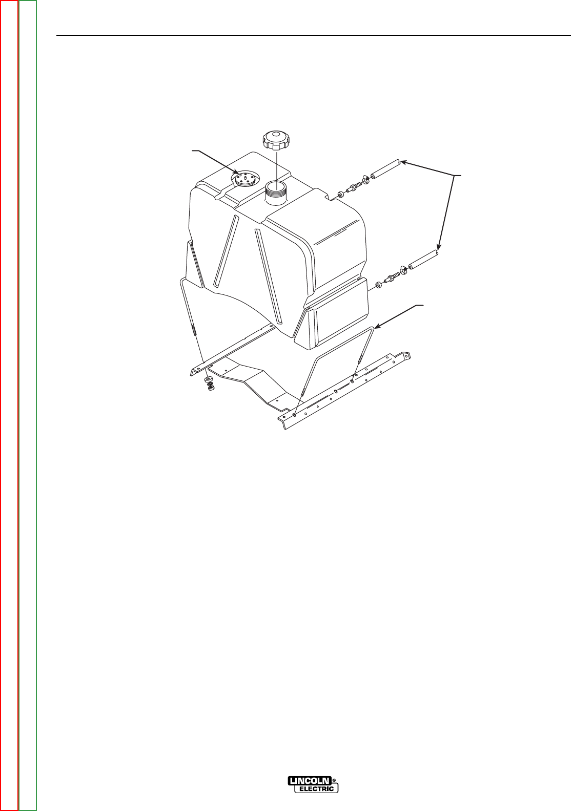
PLUG
FUEL
LINES
U-BOLTS (2)
LEADS #229
AND #5J
{
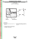
FIGURE F.19 – FUEL TANK REMOVAL
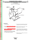
STATOR/ROTOR REMOVAL AND REPLACEMENT PROCEDURE
(CONTINUED)
PROCEDURE
1. Turn the engine off.
2. Perform the Case Cover Removal Procedure,
including the output panel.
3. Perform the Output Rectifier Bridge and
Choke Removal Procedure.
4. Using a 3/8” wrench, remove leads #229 (white)
and #5J from the fuel level sensor. See Figure
F.19. Label the leads for reassembly.
5. Turn the fuel off at the shutoff valve. Remove
and plug the fuel return line. See Figure F.19.
6. Remove and plug the lower fuel line. Pull it
through the firewall. See Figure F.19.
7. Using a 9/16” socket wrench, remove the four
lock nuts, washers, and rubber washers from
the fuel tank mounting U-bolts. See Figure
F.19.
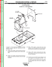
8. Carefully remove the U-bolts and lift the fuel
tank from the machine.
TROUBLESHOOTING & REPAIR
F-96 F-96
VANTAGE® 400
Return to Section TOC Return to Section TOC Return to Section TOC Return to Section TOC
Return to Master TOC Return to Master TOC Return to Master TOC Return to Master TOC