


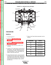
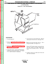
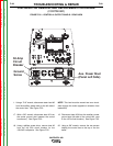
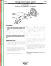
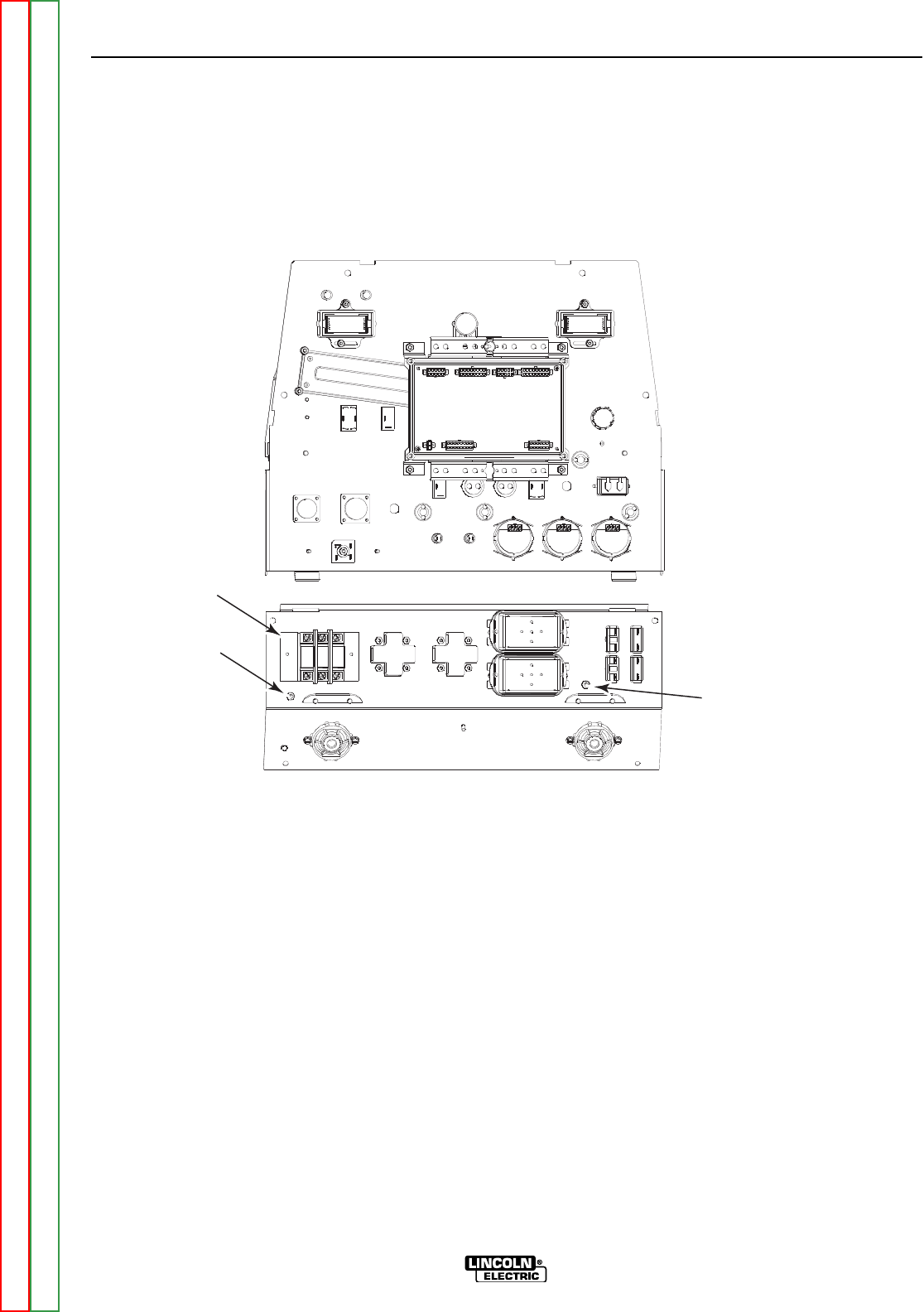
50 Amp
Circuit
Breaker
Ground
Screw
Aux. Power Stud
(Panel Left Side)
FIGURE F.22 – CONTROL & OUTPUT PANELS - REAR VIEW
STATOR/ROTOR REMOVAL AND REPLACEMENT PROCEDURE
(CONTINUED)
1. Using a 7/16” wrench, disconnect stator lead #6
from the auxiliary power stud on the left side of
the control box. See Figure F.22.
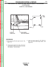
17. With a 3/8” wrench, disconnect lead #5 from
the center ground stud (nearest the control
transformer). See Figure F.22.
18. Using a phillips screw driver, remove lead #3
from the top 50A circuit breaker for the
120/240V receptacle. See Figure F.22.
NOTE: This lead must be wound two turns clock-
wise through the toroid (opposite in direction from
leads #6A).
19. Disconnect lead #5A from the auxiliary power
ground stud (left side of the control box, next
to the 120V circuit breaker). See Figure F.22.
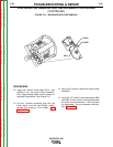
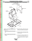
20. Using a 3/8” wrench, remove the two screws
holding the control box to the top of the fan
baffle.
TROUBLESHOOTING & REPAIR
F-99 F-99
VANTAGE® 400
Return to Section TOC Return to Section TOC Return to Section TOC Return to Section TOC
Return to Master TOC Return to Master TOC Return to Master TOC Return to Master TOC