


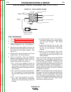
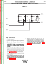
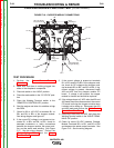

B1
B2
B3
B6
B5
B4
23
25
SL302
SL301
HL W9
HL W4
HL W6
SL14
SL13
B8
HL W8
HL W5
HL W11
LED1LED1
LED4LED4
LED2LED2
LED3LED3
L12683-1
LED1 (B1,B2,B3)
Chopper Working
LED3 (B4,B5,B6)
Chopper Working
LED4
PWM Signal
LED2
Voltage from
Rectifier
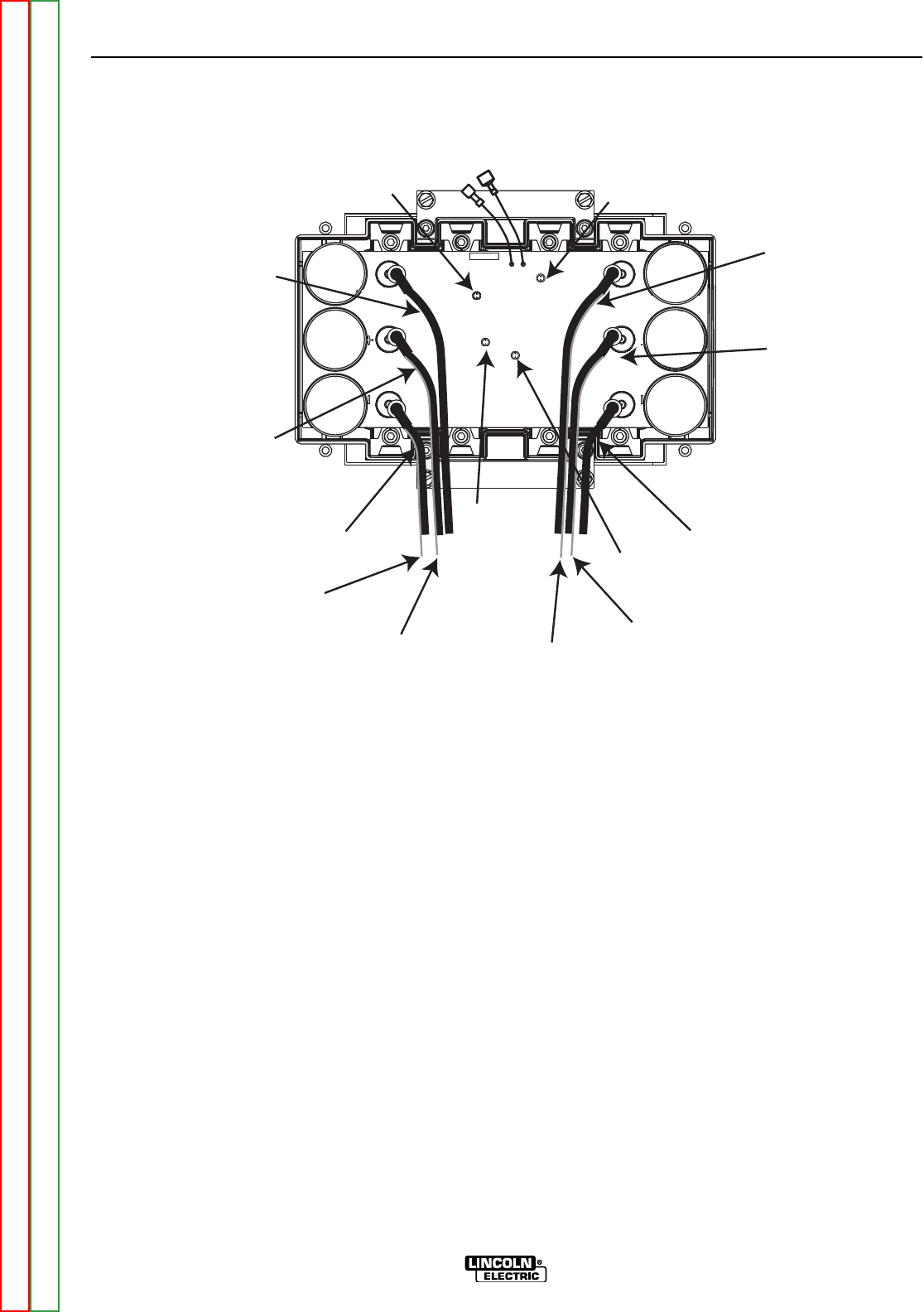
FIGURE F.16 - CHOPPER MODULE CONNECTIONS
CHOPPER MODULE FUNCTION TEST (CONTINUED)
TEST PROCEDURE
1. Perform the Case Cover Removal
Procedure.
2. Make sure that there is nothing plugged into
either of the Amphenol receptacles.
3. Place idle switch in the “HIGH” position.
4. Place the mode switch in the “CC-STICK” posi-
tion.
5. Place the Welding Terminal switch in the
“REMOTELY CONTROLLED” position.
6. Start the engine and allow it to stabilize at high
idle RPM.
7. Check for 80 to 100 VDC at terminals B1- to
B2+ and B4- to B5+ of the chopper module.
See wiring diagram and figure #1.
8. If the correct DC voltage is not present at ter-
minals B1- to B2+ and B4- to B5+, check for
damaged conductors or faulty connections
between the chopper module, the output recti-
fier, and the stator weld winding. See Figure
F.17. See the wiring diagram. Perform the
Stator Voltage Tests, and the Output
Rectifier Test.
9. If the correct voltage is present at terminals
B1- to B2+ and B4- to B5+ of the chopper mod-
ule, check for DC voltage at the chopper mod-
ule terminals B2+ to B3-, and B5+ to B6-, If sig-
nificant voltage is present, disconnect leads
#23 and #25 from the chopper module PC
board. If voltage is still present, the copper
module is shorted and should be replaced.
10. If the voltage drops to 0 VDC after the #23 and
#25 leads have been disconnected, the control
PC board is driving the chopper module when
it should not be doing so. Reconnect the #23
and #25 leads and perform the Weld Control
Board Gate Drive Test.
11. Reconnect leads #23 and #25, and place the
Welding Terminal switch in the “WELD TERMI-
NALS ON” position.
12. Check for about 58 VDC between Chopper
Module Terminals B2+ to B3-, and B5+ to B6
and between the welder output terminals. See
Figure F.16. See the wiring diagram.
TROUBLESHOOTING & REPAIR
F-62 F-62
VANTAGE® 400
Return to Section TOC Return to Section TOC Return to Section TOC Return to Section TOC
Return to Master TOC Return to Master TOC Return to Master TOC Return to Master TOC