


G-11
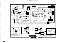
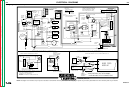
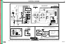
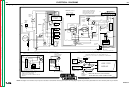
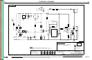
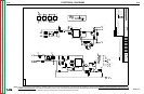
ELECTRICAL DIAGRAMS
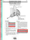
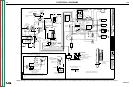
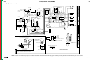
CLASSIC II
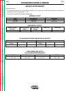
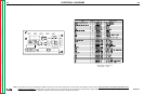
Idler PC Board (l9902) Components
IDENTIFICATION
PART NO.
REQ'DITEM
CAPACITORS = MFD/VOLTS
INDUCTANCE = HENRYS
N.A.
N.A.
N.A.
CR1
C1
C2
C3
C4
C5
C6
C7
C8
C9
C10
C11
C12
C13
DZ1
DZ2
DZ3
D1
D2
D3
D4
D5
D6
D7
J1 J2
Q1
Q2
Q3 Q4
R1
R2
R3
R4
R5
R6
R7
R8
R9
R10
R11
R12
R13
R14
R15
R16
R17
R18
R19
R20
R21
R22
R23
R24
R25
R26
R27
R28
R29
R30
R31
R32
R33
R34
R35
R36
R37
R38
R39
R40
R41
R42
R43
TP1
X1
X2
X3
X4
X5
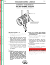
IDLER ENGINE SHUTDOWN
R
B1
N.A. THIS DEVICE IS SUBJECT TO DAMAGE BY STATIC
ELECTRICITY. SEE E2454 BEFORE HANDLING.
L9902
G-11
Return to Section TOC Return to Section TOC Return to Section TOC Return to Section TOC
Return to Master TOC Return to Master TOC Return to Master TOC Return to Master TOC
NOTE: Lincoln Electric assumes no responsibility for liablilities resulting from board level troubleshooting. PC Board repairs will invalidate your factory warranty. Individual Printed Circuit Board Components are not
available from Lincoln Electric. This information is provided for reference only. Lincoln Electric discourages board level troubleshooting and repair since it may compromise the quality of the design and may result
in danger to the Machine Operator or Technician. Improper PC board repairs could result in damage to the machine.